Loading display configuration, Tile mode, Creating a tile mode – HP LD5535 55-inch LED Digital Signage Display User Manual
Page 31
Loading display configuration
You can import (load) the saved settings to restore the display settings easily.
The following describes how to import the saved display settings.
1.
Right-click a display for which the settings are to be imported and restored.
2.
Click Load Configuration from the shortcut menu. The Open dialog appears.
3.
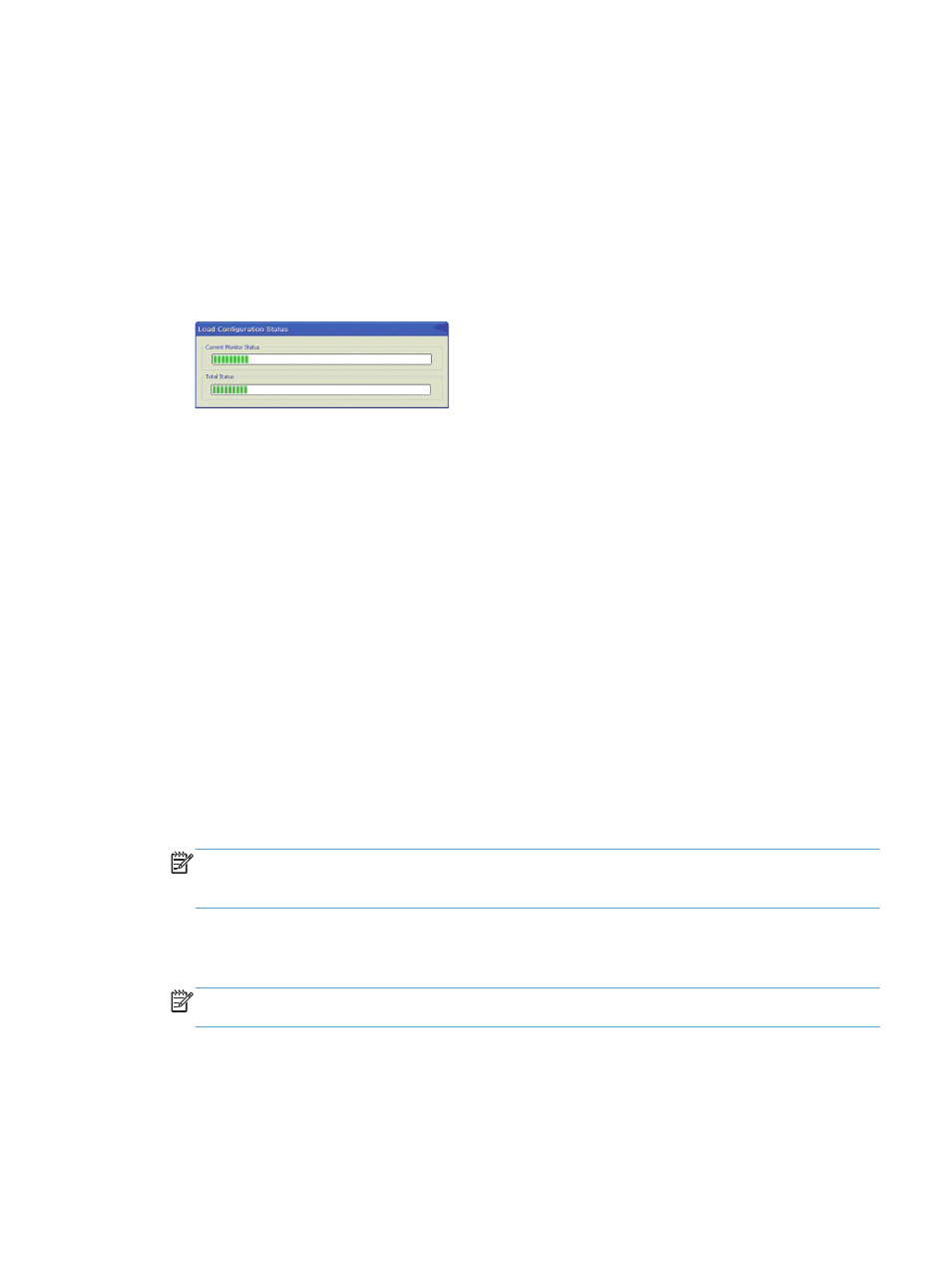
Select the display settings file to import, and then click Open. The selected settings are imported for the
display, and the Load Configuration Status dialog shows the progress. The Configuration load
complete message appears when they are successfully imported.
Tile Mode
Tile Mode is used to set up displays in a matrix or array (video wall) so that an image can be sent to the first
display in the matrix or array and extend that image across all the multiple displays in the video wall
automatically by using the display’s internal scalar capabilities. HP Network Sign Manager provides the
capability to set up each of the displays and define the size of the matrix. Before setting up Tile Mode, all the
displays within the matrix must be connected via a daisy chain and must be added to a Group in the
Registration Window. The Tile tab can also be used to adjust the settings for select digital signage display
models Tile Mode matrix.
Creating a Tile Mode
1.
Select the group that contains all of the displays to be used in Tile Mode (Video Wall) from the
Registration Window.
2.
Select the Tile tab. The Tile Mode Wizard appears as shown below.
3.
To create a new Tile Mode, select Create Tile Mode. To modify a previous Tile Mode, select Adjust Tile
Mode.
4.
On the next screen, select the number of columns and rows in the matrix and click on the Set button.
Then click Next.
NOTE:
The tile size cannot exceed the maximum number of displays in the selected group. The
maximum size of Tile Mode supported is 5 x 5 video wall and the displays can be in either landscape or
portrait orientation.
5.
A graphic will appear illustrating the matrix configuration selected. Assign the display from the
Registration Window to its position in the matrix by setting the corresponding number in the icon as
shown below. After setting the number in each icon to the display number, click Next.
NOTE:
Use the Add Tag feature in the Registration Window to add a description to the IP address of
the display to help identify the position of the display in the wall or matrix.
6.
Select the input source to use for all of the displays within the video wall or matrix from the pull down
menu. All the displays must be daisy chained using the video source selected. (See the display User
Guide for details on daisy chain for Tile Mode.) The Group matrix should automatically show the size of
the matrix.
Tile Mode
25