Jumpering the byte-wide socket, Byte-wide socket signals – Ampro Corporation 486E User Manual
Page 68
Little Board™/486e Technical Manual
2–52
Jumpering the Byte-Wide Socket
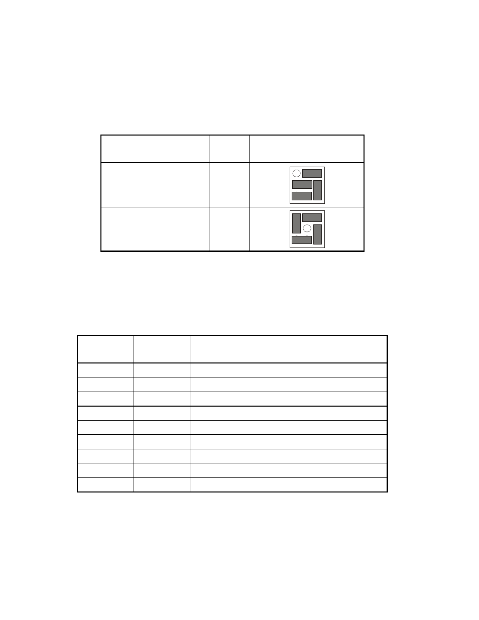
You must jumper the byte-wide socket for the devices you install. Jumper array W2 configures S0
for a particular device type. Table 2–38 shows how to install jumpers for supported memory
devices.
Table 2–38. EPROM Jumpering for S0 (W2)
EPROM
Typical Devices
Pins
Jumper Diagram
128K EPROM - 27C010
256K EPROM - 27C020
32
1
3
7
9
512K EPROM - 27C040
1M EPROM - 27C080
32
1
3
7
9
Byte-Wide Socket Signals
A jumper W2 for S0, configures the byte-wide sockets for specific memory devices. Table 2–39 lists
the signals that appear on the pins of W2.
Table 2–39. Byte-Wide Jumper Pin Signals (W2)
W14 Pin
Signal
Name
Description
1
A18
Address A18 (static)
2
Pin 1
Connection to pin 1 of the byte-wide socket
3
A19
Address A19 (static)
4
Pin 31
Connection to pin 31 of the byte-wide socket
5
-SMEMW
Write strobe
6
Pin 29
Connection to pin 29 of the byte-wide socket
7
A15
Address SA15 from the expansion bus
8
Pin 3
Connection to pin 3 of the byte-wide socket
9
A14
Address SA14 from the expansion bus