Flat panel/crt video controller, Connecting a crt (j5) – Ampro Corporation 486E User Manual
Page 49
Product Reference
2–33
Flat Panel/CRT Video Controller
The Little Board/486e CPU provides an integrated high-performance super VGA video controller
that supports both CRT and flat panel displays. Table 2–27 provides a summary of the Video
Interface connectors and their specific use and features are described in the following sections.
It is possible to disable the on-board video controller by removing jumpers W11 and W12. This can
help developers recover from a misprogrammed video BIOS by allowing the installation of a second
display card. To re-enable the video controller, install W11 and W12 and reset the system.
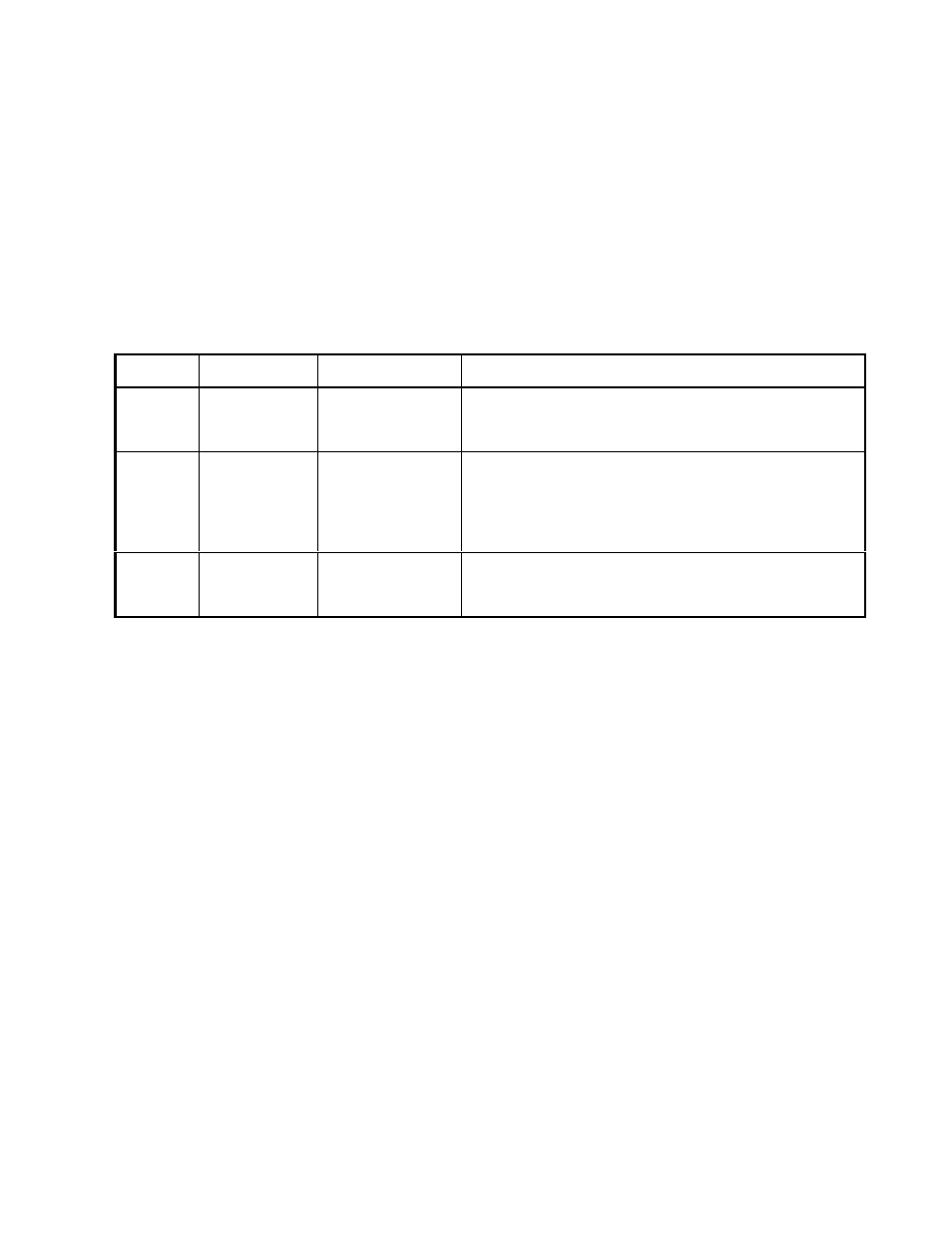
Table 2–27. Video Connector Summary
Name
Connector
Pins/Type
Description
Flat
Panel
J3
50-pin Shrouded
.100 Header
Provides connections for a broad array of standard
flat panel displays. Intended for standard 50-wire
ribbon cable.
LCD
Bias
Supply
Option
J4
12-pin Shrouded
.100 Header
Ampro provides a small add-on board that will supply
the Vee voltage for most common LCD flat panel
displays. It mounts to this connector. For details
about the Vee Supply Option, refer to it’s section,
below.
CRT
J5
10-pin Shrouded
.100 Header
Provides connections for a CRT display. To connect
to a standard CRT cable, use a short transition cable
to a DB-15 connector.
Connecting a CRT (J5)
Analog video signals from the video controller appear on 10-pin dual row header, J5. These signals
are compatible with the standard video monitors commonly used with desktop PCs. Specifications
for compatible monitors are provided in Chapter 3.
Normally, signals from J5 are connected to a standard DB-15 video connector by a transition cable
made from a ribbon cable connector and a short length of 10-wire ribbon cable. The transition cable
can connect the video signals to a bulkhead-mounted DB-15 or DB-9 connector, allowing any
standard CRT to be easily connected using a standard monitor video cable. Table 2–28 gives the
signal pinout of J5 and pin connections for a DB-15 connector. Pin connections for a DB-9
connector, used for some monitors are also provided. Table 2–29 26 shows manufacturer’s part
numbers for mating connectors to J5.