Ide interface configuration – Ampro Corporation 486E User Manual
Page 47
Product Reference
2–31
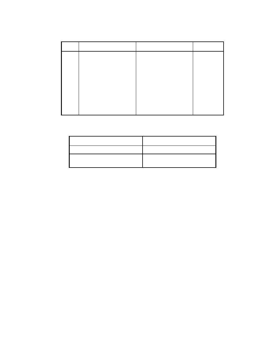
Table 2–25. IDE Drive Interface Connector (J12) (continued)
Pin
Signal Name
Function
In/Out
33
HOST A1
Drive address 1
OUT
34
RSVD
Reserved
N/C
35
HOST AD0
Drive address 0
OUT
36
HOST AD2
Drive address 2
OUT
37
-HOST CS0
Chip select
OUT
38
-HOST CS1
Chip select
OUT
39
-HOST SLV/ACT
Drive active/drive slave
10K Pull-up
40
GND
Ground
OUT
Table 2–26. J12 Mating Connector
Connector Type
Mating Connector
Ribbon
3M 3417-7600
Discrete Wire
MOLEX Housing 22-55-2402
PIN 16-02-0103
IDE Interface Configuration
Use SETUP to specify the IDE hard disk drive type. Refer to the SETUP section later in this
chapter for details.
If a drive type whose displayed parameters match the drive being used is not found use drive type 48 or 49. These
permit manual entry of the drive parameters described in the documentation provided by the drive’s manufacturer.
Use drive type AUTO for all IDE drives. AUTO automatically configures the drive type parameters from
information provided by the drive itself.