Ampro Corporation 486E User Manual
Page 42
Little Board™/486e Technical Manual
2–26
Note
For maximum reliability, keep the cable between the board and the
device it drives to 10 feet or less in length.
Register Bit Definitions
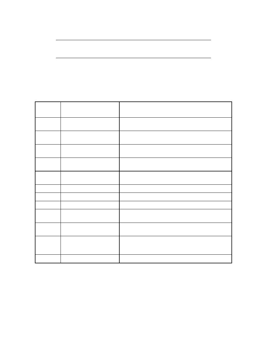
Table 2–21 defines the register bits shown in the Signal Name or Function column of Table 2–19.
Table 2–21. Standard and PS/2 Mode Register Bit Definitions
Signal
Name
Full Name
Description
-ERR
Error
Reflects the status of the -ERROR input. 0 means
an error has occurred.
SLCT
Printer selected status
Reflects the status of the SLCT input. 1 means a
printer is on-line.
PE
Paper end
Reflects the status of the PE input. 1 indicates
paper end.
-ACK
Acknowledge
Reflects the status of the ACK input. 0 indicates a
printer received a character.
-BUSY
Busy
Reflects the complement of the BUSY input. 0
indicates a printer is busy.
STROBE
Strobe
This bit is inverted and output to the -STROBE pin.
AUTOFD
Auto feed
This bit is inverted and output to the -AUTOFD pin.
-INIT
Initiate output
This bit is output to the -INIT pin.
SLC
Printer select input
This bit is inverted and output to the pin. It selects
a printer.
IRQE
Interrupt request enable
When set to 1, interrupts are enabled. An interrupt
is generated by the positive-going -ACK input.
PCD
Parallel control direction
When set to 1, port is in input mode. In printer
mode, the printer is always in output mode
regardless of the state of this bit.
PD0-PD7
Parallel Data Bits