Parallel port connector (j15) – Ampro Corporation 486E User Manual
Page 41
Product Reference
2–25
Parallel Port Connector (J15)
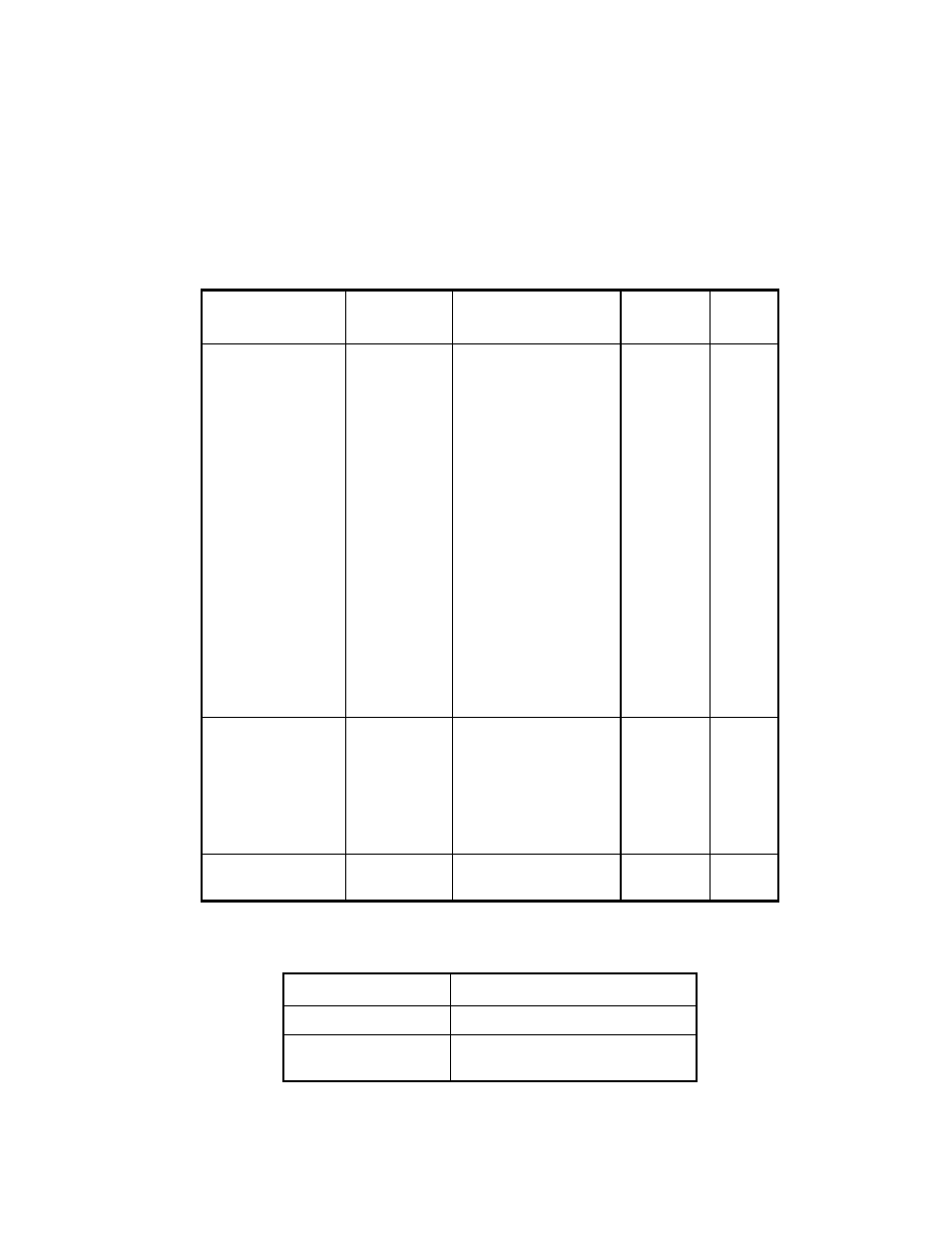
Connection to the parallel port is through connector J15. Table 2–19 details the J15 pinout and
signal definitions. Use a flat ribbon cable between J15 and a female DB25 connector. The table
describes the connections from the header pins to the DB25 connector. Table 2–20 gives
manufacturer’s part numbers for mating connectors for J15.
Table 2–19. Parallel Port Connector
J15 Pin
Signal
Name
Function
In/Out
DB25
Pin
1
3
5
7
9
11
13
15
17
19
21
23
25
-STROBE
Data 0
Data 1
Data 2
Data 3
Data 4
Data 5
Data 6
Data 7
-ACK
BUSY
PAPER
OUT
SEL OUT
Output data strobe
LSB of printer data
MSB of printer data
Character accepted
Cannot receive data
Out of paper
Printer selected
OUT
I/O
I/O
I/O
I/O
I/O
I/O
I/O
I/O
IN
IN
IN
IN
1
2
3
4
5
6
7
8
9
10
11
12
13
2
4
6
8
26
-AUTOFD
ERROR
-INIT
SEL IN
N/A
Autofeed
Printer error
Initialize printer
Selects printer
Key pin
OUT
IN
OUT
OUT
14
15
16
17
10,12,14,
16,18,20, 22,24
GROUND
Signal ground
N/A
18-25
Table 2–20. J15 Mating Connector
Connector Type
Mating Connector
Ribbon
3M 3399-7600
Discrete Wire
MOLEX Housing 22-55-2262
Pin 16-02-0103