Utility interface (j5), Keyboard, Mouse – Ampro Corporation 420 User Manual
Page 42: Battery, Reset switch, Speaker, Keyboard mouse, Battery reset switch speaker
Chapter 3
Hardware
36
Reference Manual
CoreModule 420
Utility Interface (J5)
The Utility interface provides various utility and I/O signals on the module and consist of a 10-pin, 0.1"
header. The Super I/O chip drives most of the signals on the Utility interface. Table 3-15 provides the
definition of the interface signals on the utility interface.
•
Keyboard and PS/2 Mouse
• Battery
• Reset Switch
• Speaker
Keyboard
The signal lines for an AT or PS/2 keyboard are provided through the Utility interface (J5) to the Super
I/O controller (U13). Refer to Table 3-15 for pin-signal information.
Mouse
The signal lines for a PS/2 mouse are provided through the Utility interface (J5) to the Super I/O
controller (U13). Refer to Table 3-15 for pin-signal information.
Battery
An external battery input connection is provided through the Utility interface (J5) to support a battery
backup for the CMOS RAM and the RTC (Real Time Clock). Refer to Table 3-15 for pin-signal
information.
Reset Switch
An external reset switch provides the reset signal through the Utility interface (J5) to a reset circuit,
which drives the STPC ATLAS CPU (U14). Refer to Table 3-15 for pin-signal information.
Speaker
The speaker signal provides sufficient signal strength to drive a 1W 8
Ω
“Beep” speaker through the
Utility interface (J5) at an audible level. The speaker signal is driven from an on board amplifier and the
STPC ATLAS CPU (U14). Refer to Table 3-15 for pin-signal information.
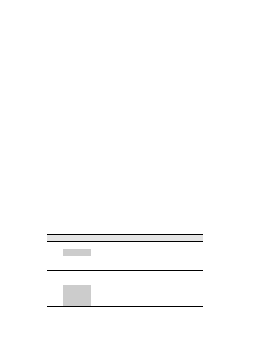
Table 3-15. Utility Interface Pin/Signal Descriptions (J5)
Pin #
Signal
Description
1
SPKR
Speaker Output
2
BATV-
Ground return
3
RESETSW*
External Reset Switch signal
4
MDATA
Mouse Data input
5
KBDATA
Keyboard Data input
6
KBCLK
Keyboard Clock input
7
GND
Ground
8
KMPWR
Keyboard /Mouse power (+5V) output
9
BATV+
Real time battery voltage (3.6V Type/ 4.0V Max) input
10
MCLK
Mouse Clock input
Notes: The shaded area denotes power or ground. The signals marked with * indicate active low.