Ampro Corporation 420 User Manual
Page 25
Chapter 3
Hardware
CoreModule 420
Reference Manual
19
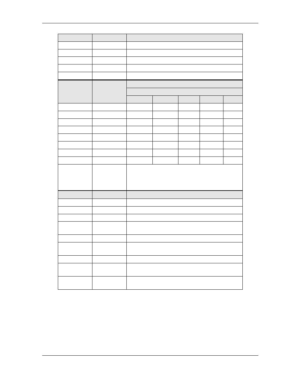
Table 3-1. Memory Map (continued)
Address
Size
Use
0400 0000
1 MB
RAM or Unused if Framebuffer is set to 1 MB or more
03F0 0000
1 MB
RAM or Unused if Framebuffer is set to 2 MB or more
03E0 0000
1 MB
RAM or Unused if Framebuffer is set to 3 MB or more
03D0 0000
1 MB
RAM or Unused if Framebuffer is set to 4 MB
03C0 0000
44 MB
RAM
Use
Memory hole size selected
Address
Size
8 MB
4 MB
2 MB
1 MB
0 MB
0100 0000
1 MB
H
H
H
H
R
00F0 0000
1 MB
H
H
H
R
R
00E0 0000
1 MB
H
H
R
R
R
00D0 0000
1 MB
H
H
R
R
R
00C0 0000
1 MB
H
R
R
R
R
00B0 0000
1 MB
H
R
R
R
R
00A0 0000
1 MB
H
R
R
R
R
0090 0000
1 MB
H
R
R
R
R
R = RAM
H = Memory Hole, forwarded to ISA
The board can be configured to have access to the 1 MB
Flash anywhere in the memory hole, on 1 MB alignment.
Address
Size
Use
0080 0000
7 MB
RAM
0010 0000
128 kB
Shadowed BIOS
000E 0000
8 kB
Unused
000D E000
8 kB
DiskOnChip, if DC000-DDFFF window selected.
Unused if no DOC present.
000D C000
56 kB
Unused
000C E000
8 kB
DiskOnChip, if CC000-CDFFF window selected.
Unused if no DOC present.
000C C000
48 kB
Unused
000C 0000
128 kB
Unused, reserved for Video RAM, or
in SMI mode, mapped to RAM
000A 0000 -
0000 0000
640 kB
Base memory