Block diagram, Figure 2-2. block diagram – Ampro Corporation 420 User Manual
Page 15
Chapter 2
Product Overview
CoreModule 420
Reference Manual
9
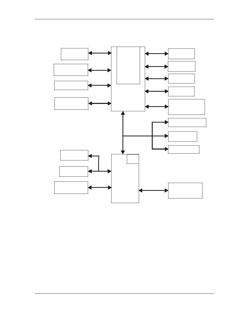
Block Diagram
Figure 2-2 shows the functional components of the module.
Speaker
STPC
Atlas
(Computer
in a Chip)
GPIOs (8)
IDE Devices
(
)
HDD, Compact Flash,
CD-ROM, etc.
Ethernet
Controller
Memory
(SDRAM)
CPU
Core
Host-
Peripheral
Interface
Super I/O
Controller
Floppy Drive
BIOS
Internal PCI
Bus
Parallel Port
PC/104 Interface
Bytewide
Socket
ISA Bus
Utility Interface
(Keyboard, Mouse,
External Bat. etc)
Video (CRT/TFT)
RTC
Serial Ports
(Serial 3 & 4)
Serial Ports
(Serial 1 & 2)
USB Port
I C Interface
2
C
M
42
0b
lk
d
iag
Figure 2-2. Block Diagram