Ampro Corporation 420 User Manual
Page 34
Chapter 3
Hardware
28
Reference Manual
CoreModule 420
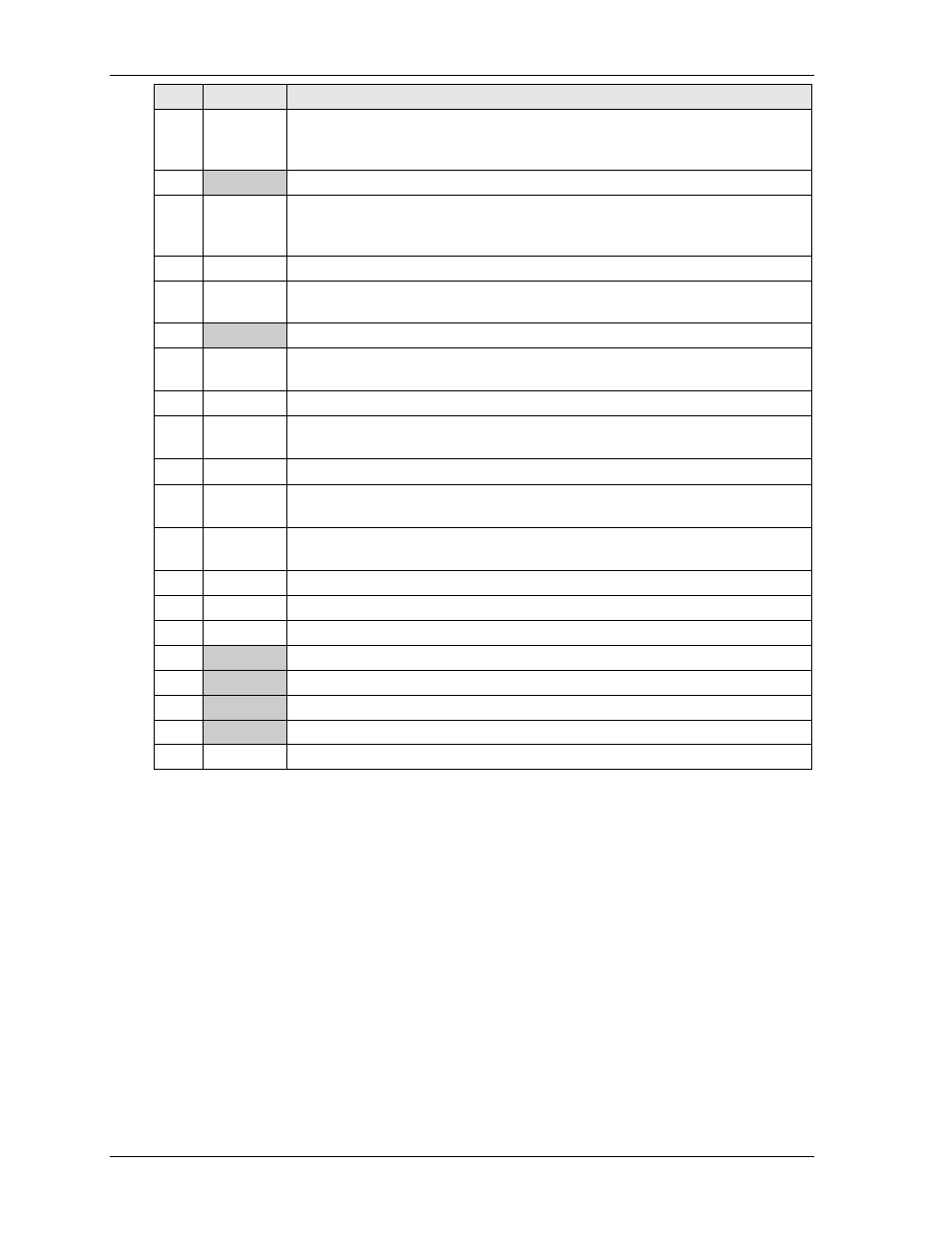
Pin #
Signal
Description
25
PIOR*
Drive I/O Read – Strobe signal for read functions. Negative edge enables data
from a register or data port of the drive onto the host data bus. Positive edge
latches data at the host.
26
GND
Ground
27
IOChRdy
I/O Channel Ready – When negated, extends the host transfer cycle of any host
register access when the drive is not ready to respond to a data transfer request.
High impedance if asserted.
28
Reserved
Reserved – Not used (through 470 ohm resistor to ground)
29
PDACK*
DMA Channel Acknowledge – Used by the host to acknowledge data has been
accepted or data is available. Used in response to DMARQ asserted.
30
GND
Ground
31
PIRQ
Interrupt Request – Asserted (IRQ 14) by drive when it has pending interrupt
request (PIO transfer of data to or from the drive to the host).
32
NC
Not connected
33
LA18
Latch Address 18 – Used to indicate which byte in the ATA command block or
control block is being accessed.
34
NC
Not connected (through 0.047
µf capacitor to ground)
35
LA17
Latch Address 17 – Used to indicate which byte in the ATA command block or
control block is being accessed.
36
LA19
Latch Address 19 – Used to indicate which byte in the ATA command block or
control block is being accessed
37
CS1*
Chip Select 1 – Used to select the host-accessible Command Block Register.
38
CS3*
Chip Select 3 – Used to select the host-accessible Command Block Register.
39
Reserved
Reserved – Not used
40
GND
Ground
41
+5V
+5 volts ±5% supply
42
+5V
+5 volts ±5% supply
43
GND
Ground
44
NC
Not connected
Notes: The shaded area denotes power or ground. The signals marked with * indicate active low.