Sterlco GH-M Series Extrusion Control Weigh Hoppers User Manual
Page 49
Chapter 7: Appendix
49 of 60
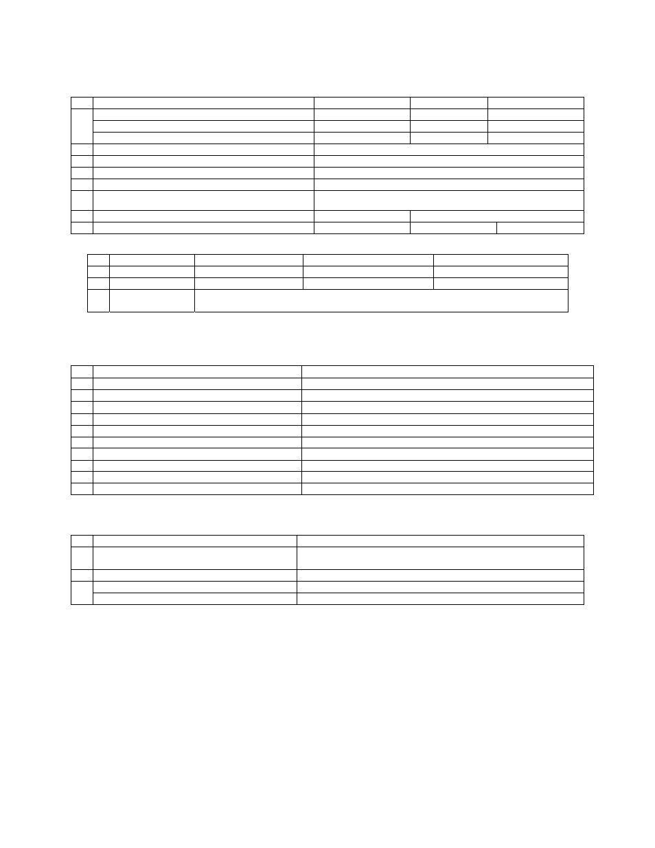
Figure 57: Typical Surge Hopper Assembly Parts List
# DESCRIPTION
010
020
040
Lid (Smaller vacuum receivers)
08223-1
872.00769.00
872.00830.00
Lid (Larger vacuum receivers)
NA
872.00783.00
-
1
Lid (Tube Stub for Mezz. Mounted GH Hopper)
08223-2
-
-
2
1/8” NPT fitting
35085K, 35086K
3
1/4” NPT fitting
35154, 35155
4
Bulkhead 35146
5
Brass elbow
35118
6
24V DC Solenoid
33128
7
Dump cone
15370
15237
8
Air cylinder
33126
33073
33011G
Figure 60: Typical Weigh Hopper Assembly Parts List
# DESCRIPTION
010
020
040
1
WEIGH HOPPER
822.00382.00 822.00383.00
822.00384.00
2
LOAD CELL
61-1010E-10KG
A0564528
A0564546
3
LOAD CELL
BRACKET
872.00669.00
Figure 64: Typical Allen-Bradley Controller Main Parts List
# Description
ALL
MODELS
1
Allen-Bradley PLC MicroLogix 1500
A0565880
2
Thermocouple Input Card
A0565375
3
Allen-Bradley PLC Base Unit
A0565881
4
24V DC Power Supply
A0563932
5
12V DC Power Supply
739.00027.00
6
Alarm Light Yellow Strobe 24V DC
A0565889
7
Glass Fuse – 3.0 amp (115v unit)
A0542207
8
Ethernet Module (optional)
A0563939
9
Ethernet Module cable
A0565898
10
120V Light (power switch)
715.01034.02
Figure 65: Typical Allen-Bradley Display Main Parts List
# Description
All
MODELS
1
Allen-Bradley Panelview Touchscreen Display
PV 550 (DF-1 protocol)
892.001489.00
2
Enclosure Mounting Feet
A0567132
Display – 8 ft Connection Cable
A0565856
3
Display – 50 ft Connection Cable
A0565899