Dc wiring options, Operation, Truepower – ProMariner TruePower 600-1200 User Manual
Page 10
8
I n s t a l l a t i o n G u i d e l i n e s
DC Wiring Options
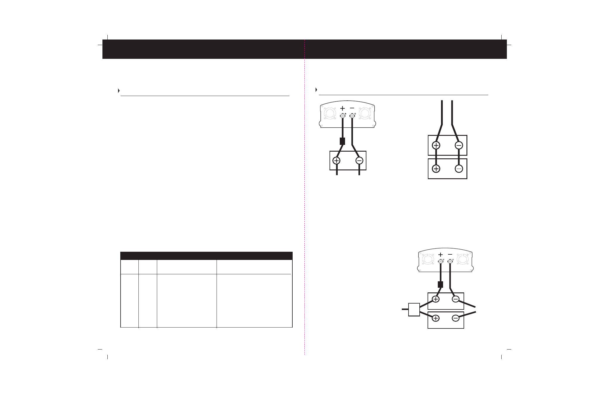
To obtain sufficient battery capacity, you may need to use more than one battery.Two
identical batteries can be connected + to + and – to – in a parallel system, doubling
capacity. We recommend that you do not connect batteries from different
manufacturers, or with different amp-hour ratings in parallel as decreased battery
life may result. See figure 3 below.
Figure 3) This wiring diagram
displays a battery configuration
for Medium-Duty applications.
Figure 2) Displays 2 x 12volt batteries
connected in a parallel system that
doubles the capacity and maintains
the 12v voltage requirement of your
inverter. This battery bank requires a
battery charging system.
Figure 1) This wiring setup displays
an inverter connected directly to
the engine battery for light-duty
applications.
*For an ABYC E-11 compliant
installation, customer supplied
fuse, 7" from battery
TruePower
*fuse
POS
NEG
Boat/
Vehicle
Battery
*For an ABYC E-11 compliant
installation, customer supplied
fuse, 7" from battery
11
O p e r a t i o n
Operation
The ON/Off switch turns the TruePower Inverter to ON or to Off.
In the ON position, the Inverter /Fault LED light will illuminate Green. The TruePower
begins inverting and provides modified sine wave power.
In the Off position the inverter draws no current from the battery.
Bat’ Saver mode allows the user to protect from draining down the entire power of the
engine start battery, and shuts the inverter off when the battery reaches a threshold
of 11.7 volts allowing you to start your boat or vehicle. To use the Bat’ Saver mode, turn
the on / off switch to the Bat’ Saver mode.
Some appliances and tools operate using larger electric motors, tubes or capacitors
require an initial surge of power to start up. This extra surge of power required is often
called the “peak load”, “starting load” or “surge capacity”. Once such a tool or appliance
is started, it requires significantly less power to continue operation. This is commonly
referred to the “continuous load” of power.
As a rule of thumb, most often the start up or surge load of the appliance or tool will
determine if your TruePower inverter has the capability of running it. If the appliance
or tool does not start the first try, attempt switching the appliance on every 2 seconds
until the appliance turns on. If the appliance does not start after the 5th or 6th attempt,
it may require a larger surge than your inverter provides.
LED Indicators:
The two indicator lights on the front panel of the inverter illustrate the operating status
of the TruePower Inverter. See table 4 below.
Status of Indicator Lights Table
negative
positive
When the TruePower unit is on,
the Inverter light illuminates.
The Fault light illuminates
whenever there is a battery
over-voltage fault condition
(in excess of 15volts +/- 1volt),
a low battery protection
indicator (below 10volts +/-
.5volts), an output overload
condition or an over-
temperature fault condition.
Can run your appliances through the
Inverter from the battery.
Can not run appliances as the AC output
is disabled in the inverter mode. Clear
the fault condition. Reset the unit by
turning the ON/Off switch to Off and then
back to ON. The inverter may need to
cool off for a period. Reduce load,
duration of use if you have been using
for a longer period of time. If it continues
to be a problem, you may need to properly
size your inverter to your application.
Fault
Red
Power Green
Light
Color
Status
Result
TruePower
*fuse
POS
NEG
deep
cycle
auxiliary battery
to ground
boat/vehicle battery
isolator
from alternator
or charger