Installation data, Commissioning and operating information, Scope of delivery – NORD Drivesystems TI059_19140990 User Manual
Page 2: Connections, Getriebebau nord gmbh & co. kg
Getriebebau NORD GmbH & Co. KG
Rudolf-Diesel-Straße 1 · D-22941 Bargteheide
Tel.: +49 45 32 - 40 10 · Fax: +49 45 32 - 40 12 53 · www.nord.com
SK EBGR-1
1.8
Supplement to series ID
28.02.11
Rck
TI 059 19140990
2/2
1.7
Radio interference suppression C2, Supplement of brake release/application times
21.02.11
Rck
Version Amendment
Date
Name Document
Page
Signal request from
FI: ON = "Release
brake"
Brake switching
state: ON= "Brake
released"
(Brake is supplied
with current)
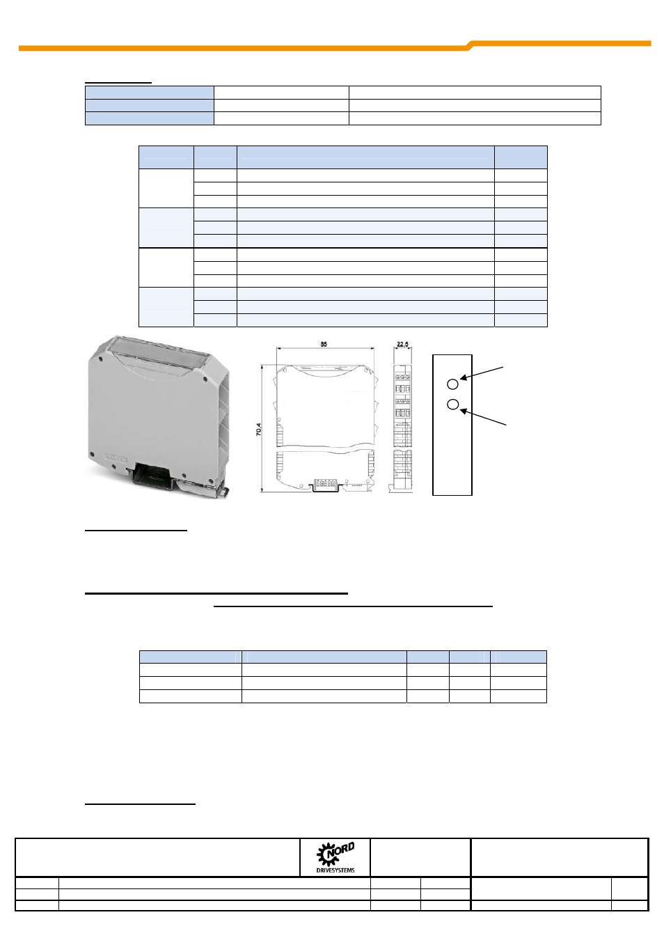
Connections
Terminals
Screw terminals
4 terminal blocks, each with 3 connections, (7.5mm spacing)
Cable cross section
0.2…2.5 mm
AWG 12-30
PE connection
via snap-on DIN rail
The snap-on rail must be grounded
Terminal
PIN
Description
Contact
No.
1
Top layer
PIN 1
Supply voltage (+24V)
44
PIN 2
Digital input for DC brake switching
C5
PIN 3
Reference potential (0V/GND)
40
2
Top layer
PIN 1
Supply voltage 380V … 500V ±10% AC (L1)
L1
E
PIN 2
Supply voltage 100V … 275V ±10% AC (L1)
L1
B
PIN 3
Reference potential (N/L2)
N/L2
3
Bottom layer
PIN 1
Supply voltage (+24V) - as for terminal 1 PIN 1 (internally bridged)
44
PIN 2
Digital output (output to SPS)
B5
PIN 3
Reference potential (0V/GND) - as for terminal 1 PIN 3 (internally bridged)
40
4
Bottom layer
PIN 1
Brake connection +
79
PIN 2
-
-
PIN 3
Brake connection -
80
Installation data:
Dimensions: [mm]
H85xW22.5xD70.4
Mounting:
Snap-on rail mounting (35mm snap-on DIN rail)
Commissioning and operating information:
Observe the brake coil voltage! Select the correct mains voltage and connect the appropriate contact.
NOTE:
Incorrect voltage or incorrect connection of the supply voltage (L1
E
or L1
B
) may cause
destruction of the SK EBGR 1 and the brake coil!
Brake coil voltage
Mains voltage
Terminal PIN
Contact No.
205V DC
230V AC
2
2 + 3
L1
B
+ N/L2
180V DC
400V AC
2
1 + 3
L1
E
+ N/L2
205V DC
460V AC or 480V AC
2
1 + 3
L1
E
+ N/L2
Brake control: Set digital input = Brake released.
The device must be provided with a 24V control voltage.
NOTE: Make a GND connection between the frequency inverter and the SK EBGR-1.
Scope of delivery:
Electronic brake rectifier SK EBGR-1 without other accessories
Terminal 1
Terminal 3
Terminal 2
Terminal 4