Connection examples, Notice, Load on the rj45 socket – NORD Drivesystems TI 275900210 User Manual
Page 3
IO-Extension
– SK EBIOE-2
TI 275900210 - 4612
3
NOTICE
Load on the RJ45 socket
The load on the contacts of the RJ45 socket must not exceed 1.2 A. When setting up a correspondingly large
network with frequency inverters and IOE modules, it may be necessary to set up two circuits in order to prevent
overload.
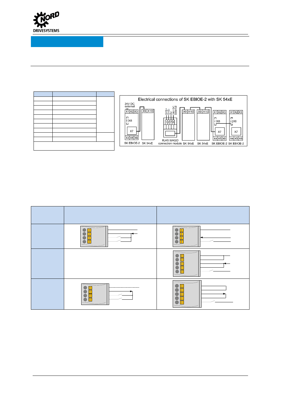
Schematic circuit diagram of electrical connection
(Terminal designations in example) Frequency inverter SK 54xE)
Terminal
Function
Device
X1
Supply / System bus
SK
E
B
IO
E
-
2
X2
AIN 2 / AOUT
X3
AIN 1
X4
DOUT
X5
DIN 3 / 4
X6
DIN 1 / 2
X7
Supply / System bus
X8
Supply / System bus
X9
Supply / System bus
SK
54xE
X10
Supply / System bus
RJ45 WAGO connection module
Part. No.: 278910300
Pos : 12 /T echnisc he I nf ormati onen/I O - Er weit er ung/ Ans chl uss beis piel e [IO E Allgemei n] @ 2\ mod_1352736753713_388. doc x @ 51105 @ 6 @ 1
Connection examples
The following connection examples are generally applicable for NORD IO modules. The number or
type of the available IOs and their configuration on the terminal rail varies according to the module.
The actual availability or the designation of the individual contacts should be obtained by reference to
the description of the connections. The technical data (e.g. load capacity) must be taken into account.
Digital signals
Control
voltage
source
Digital input
Digital output
External
supply
GND/0V
VI 24V
DIN
DIN
GND2/0V2
DOUT
VI 24V2
GND2/0V2
VI 24V
DOUT
VI 24V2
GND/0V
Internal supply
GND/0V
VO 24V
DIN
DIN
GND2/0V2
VO 24V
DOUT
VI 24V2
GND/0V