Installation, Connections – NORD Drivesystems TI 275900210 User Manual
Page 2
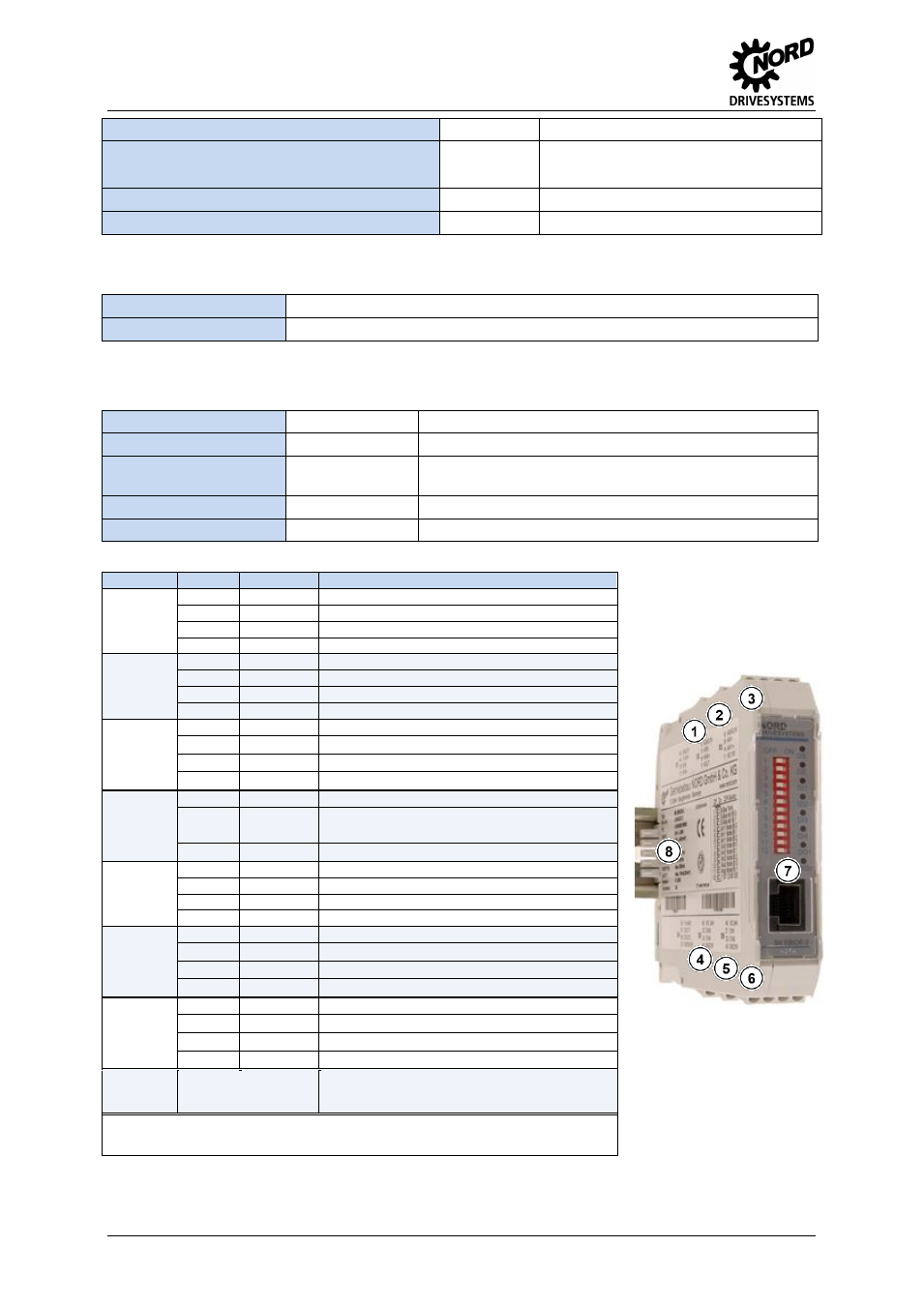
IO-Extension
– SK EBIOE-2
2
TI 275900210 - 4612
Name
Terminal
Data
Analog output - load capacity
17
≤ 10 mA (Mode: 0/2 … 10 V)
≤ 20 mA (Mode: 0/4 … 20 mA, at 5 V)
Analog output - specific information
17
Resolution: 10 Bit, accuracy: 0.25 V
RJ45 - current capacity
RJ45 7/8
≤ 1200 mA
Installation
Installation location
Inside a suitable switching cabinet
Mounting
Mounting on snap-on rail (TS 35)
Pos : 8 /T ec hnis che Inf or mationen/ IO - Er weiter ung/Ansc hlüss e [SK EBIO E-2] @ 2\ mod_1353314658836_388. doc x @ 51201 @ 6 @ 1
Connections
Terminals
Screw terminals
6 terminal blocks, each with 4 connections, (5 mm spacing)
Cable cross section
0,14 … 2,5 mm
AWG 14-26
PE connection
via snap-on DIN
rail
The snap-on rail must be earthed
Snap-on rail bus connector
Plug connector
For the serial installation of up to 8 SK EBIOE-2 modules
RJ45
RJ45 - socket
For connection via RJ45 connection cable
Terminal
Contact
Designation
Description
X1
Top
position
40
GND/0V
Reference potential (0 V / GND)
44
VI 24V
Supply voltage (+24 V - in)
78
SYS-
System bus data cable -
77
SYS+
System bus data cable +
X2
Top
position
12
AGND/0V
Analog Ground (internally connected to terminal 40)*
15
AIN2-
Analog input 2, negative
16
AIN2+
Analog input 2, positive
17
AOUT
Analog Out
X3
Top
position
12
AGND/0V
Analog Ground (internally connected to terminal 40)*
13
AIN1-
Analog input 1, negative
14
AIN1+
Analog input 1, positive
11
VO 10V
10 V Reference voltage
X4
Bottom
position
50
VI 24V2
Supply voltage (+24 V - in) for digital outputs
B1
DOUT1
Digital output 1
B2
DOUT2
Digital output 2
20
GND2/0V2
Reference potential (0 V / GND) of digital outputs
X5
Bottom
position
43
VO 24V
Supply voltage for digital inputs (+24 V - out)
C3
DIN3
Digital input 3
C4
DIN4
Digital input 4
40
GND/0V
Reference potential (0 V / GND)
X6
Bottom
position
43
VO 24V
Supply voltage for digital inputs (+24 V - out)
C1
DIN1
Digital input 1
C2
DIN2
Digital input 2
40
GND/0V
Reference potential (0 V / GND)
X7
Front
position
RJ45 - 1
SYS +
System bus data cable +
RJ45 - 2
SYS -
System bus data cable -
RJ45 - 7
GND/0V
Reference potential (0 V / GND)
RJ45 - 8
24 V
Supply voltage (+24 V
– in / out)
X8
Rear
position
Snap-on
rail
bus
connector
Connection of voltage supply and system bus to a further
SK EBIOE
-
2 module
* AGND/0V is internally connected to the reference voltage of the module GND/0V via a special
component. In order to prevent damage to the module or faults in the analog signals, the two contacts
must not be bridged
1 … 8 =
X1 … X8