Configuration, Led displays, Powerlink bus module – sk tu4-pol – NORD Drivesystems TI 275281118 User Manual
Page 4
POWERLINK Bus module – SK TU4-POL
4
TI 275281118 - 4913
Configuration
The basic configuration of the module is primarily carried out via its DIP - switches. The DIP - switch
settings are read after a "Power On" of the module.
DIP switch
Meaning
12
11
10
9
8
7
6
5
4
3
2
1
Address
N
o f
u
nc
ti
on
X
X
0
0
0
0
0
0
0
0
X
0
X
X
0
0
0
0
0
0
0
1
X
1
X
X
0
0
0
0
0
0
1
0
X
2
X
X
0
-
-
-
-
-
-
-
X
-
X
X
1
1
1
0
1
1
1
1
X
239 (largest permissible address)
0
System bus terminating resistor not set
1
System bus terminating resistor set
Access rights for remote maintenance
0
Only read access to parameters possible.
1
Read and write access to parameters possible.
0
No control possible.
1
Control is possible.
1. System bus (DIP 1)
The system bus must be terminated at both physical
ends.
2. IP address (DIP 2 - 9)
The node ID (the final byte of the IP address) can be
set via this switch and controlled in parameter P185.
The largest permissible node ID for CN is 239
3. Access rights for remote maintenance (DIP 10 – 12)
With the Ethernet protocol UDP, the module and the
connected frequency inverter can be accessed via
remote maintenance. The type of access is
determined via the DIP - switch with inputs 10 to 11.
Pos : 18 /T echnisc he I nf ormati onen/ SK xU x - Bus - Erweit erungen/ Powerlink/LED Anz eigen [ SK TU 4-PO L(-C)] @ 3\ mod_1377869059920_388.doc x @ 92007 @ 5 @ 1
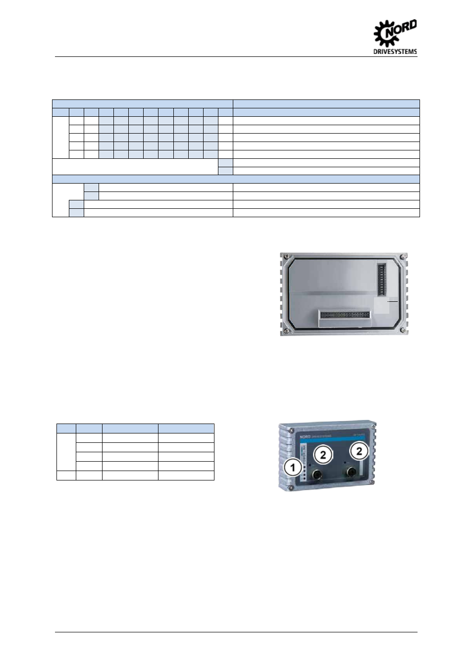
LED displays
The operating statuses of the module are visualised using LED indicators.
No.
Name
Colour
Meaning
1
BS
green
Module status
BE
red
Network Error
DS
green
Device status
DE
red
Device error
2
L/A
green
Link/Activity
Pos : 20 /T echnisc he I nf ormati onen/ SK xU x - Bus - Erweit erungen/ Powerlink/LED Anz eigen- PO WER LIN K s pezifisc he LED [POL Allgemein] @ 3\ mod_1377869060362_388.doc x @ 92032 @ @ 1
1
…
12
ON
OF
F