Connections, Configuration, Attention – NORD Drivesystems TI 275274603 User Manual
Page 2: Possible damage to devices
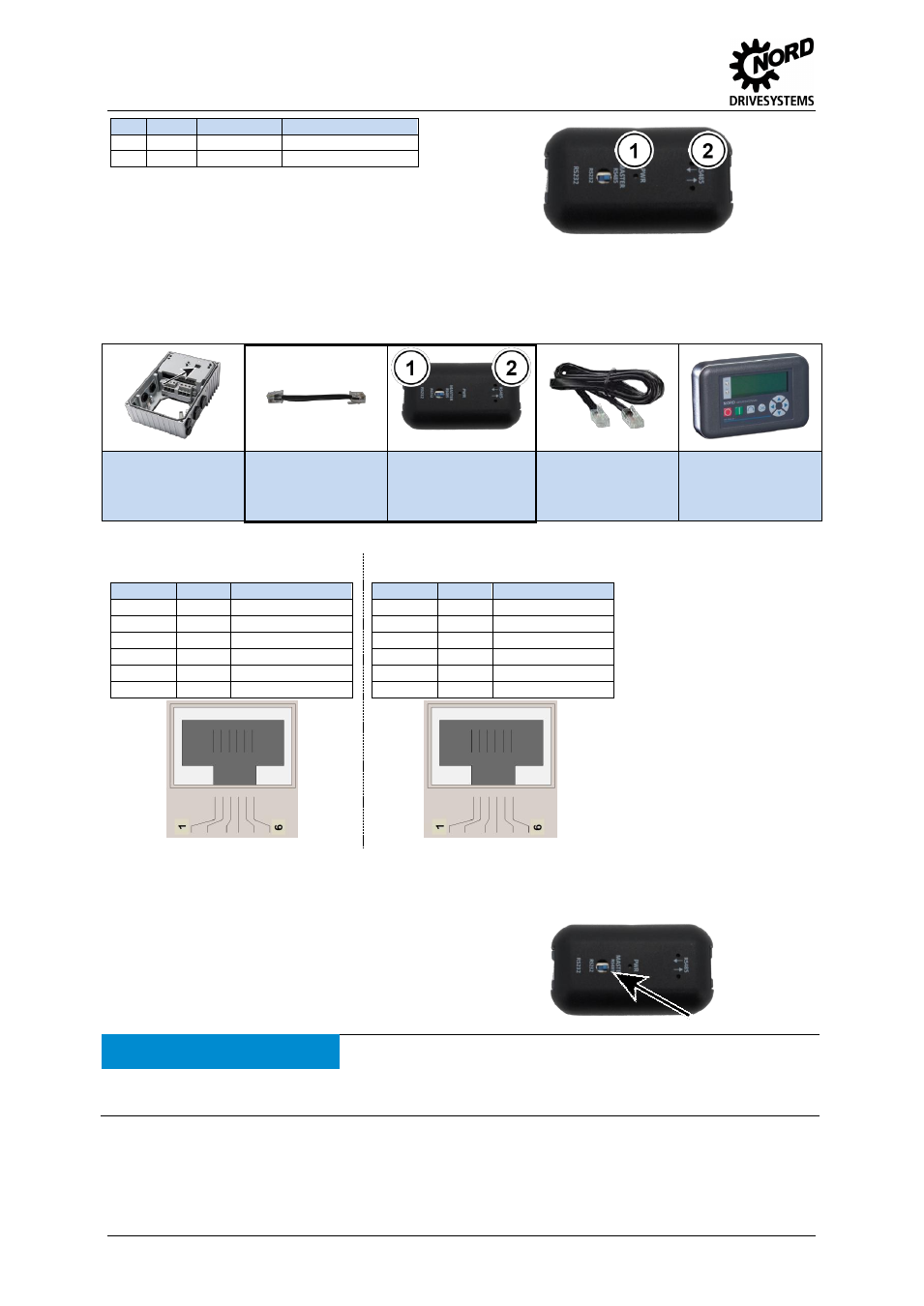
Connection extension
– SK TIE4-RS232-RS485
2
TI 275274603 - 2713
No.
Name
Colour
Meaning
1
PWR
Green
Ready for operation
2*
RS485
2x Yellow
Communication active
* Each LED indicates an intact communication direction. If an LED
does not illuminate, this indicates a fault or interruption in the relevant
communication direction.
Pos : 3 /T ec hnis che Inf or mationen/ Ansc hluss er weiter ung en [HAN , H Q,SK T IE]/U ms etz er R S 232-RS485/ Anschl üss e [SK TI E4-RS485_RS232] @ 3\ mod_1372674444498_388. doc x @ 80447 @ 5 @ 1
Connections
The converter is connected between e.g. the motor starter and the ParameterBox (see below).
Starter
(Interface: RS 232)
Connection cable
RJ12
– RJ12
(Enclosed with
converter)
Converter
SK TIE4-RS485-
RS232
Connection cable
RJ12
– RJ12
(enclosed with
ParameterBox)
ParameterBox
(Interface: RS 485)
( 1 ) Detail RJ12
– RS232
( 2 ) Detail RJ12
– RS485
Contacts 3 and 6 are
connected through! The load
must not exceed 500 mA!
RJ12 Pin
Signal
Description
1
n.c.
2
n.c.
3
GND
Earth
4
TXD
Transmission Data
5
RXD
Receive Data
6
+24V-
24 V ± 20 %
RJ12 Pin
Signal
Description
1
A (+)
RS485_A
2
B (-)
RS485_B
3
GND
Earth
4
n.c.
5
n.c.
6
+24V-
24 V ± 20 %
Pos : 4 /T ec hnis che Inf or mationen/ Ansc hluss er weiter ung en [HAN , H Q,SK T IE]/U ms etz er R S 232-RS485/ Konfig urati on [ SK TIE4-RS485-R S232] @ 3\ mod_1372670309640_388. doc x @ 80376 @ 5 @ 1
Configuration
Configuration of the converter is restricted to a DIP switch on
the front side of the converter. This determines the interface
on which the master is located.
No communication is possible if the DIP switch is not
set correctly.
ATTENTION
Possible damage to devices
Care must be taken that only one participant takes on the master function. Failure to observe this may cause
damage to the relevant drivers.
=== Ende der List e f ür T ext mar ke I nhalt ===