Operation of the threadchecker – Kaman ThreadChecker User Manual
Page 5
Copyright © 2008
Kaman Aerospace Corporation
PART NO: 860510-001A
Kaman Precision Products
Last Revised: 6/8/11
Measuring & Memory Systems
217 Smith Street
Middletown, CT 06457
www.kamansensors.com or 860-632-4442
Page 5 of 13
Operation of the ThreadChecker
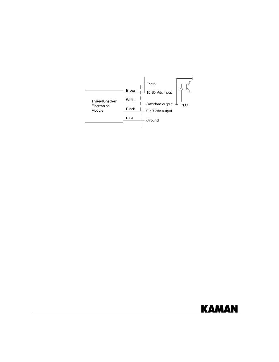
Wire colors & pin-out.
The wire colors and typical connection diagram are as follows.
Teach sequence
Before the system is first used it must have the ‘teach’ sequence run. In order to do
this you must have a representative threaded and non-threaded hole. The system can
be easily calibrated to any new sensor designed for the ThreadChecker as well as for
most hole/thread configurations with a simple calibration sequence.
1. Connect the sensor and power source to the electronics. Allow the system to
warm up for a minimum of 5 minutes.
2. With the sensor in ‘air’ (i.e. not in a hole or near any conductive material), press
and hold the ‘Teach’ button until the Thread LED blinks fast then release (more
than 1 second but less than 10 seconds), the Thread LED should blink slowly.
3. Position the sensor tip in the threaded hole and momentarily press the ‘Teach’
button. The Status LED will blink fast.
4. Position the sensor in an unthreaded or bad hole and momentarily press the
‘Teach’ button. The LED should be solid red indicating no threads present. The
system is now calibrated and ready for use.
Since the switch point is half way between these 2 points you can teach these in
reverse order (bad then good) if desired.