Differential output measurements – Kaman SMU9200 User Manual
Page 15
SMU-9000 User Manual
12
••••
Part III: Calibration
from the target, the second sensor would therefore be positioned at
minimum displacement respectively.
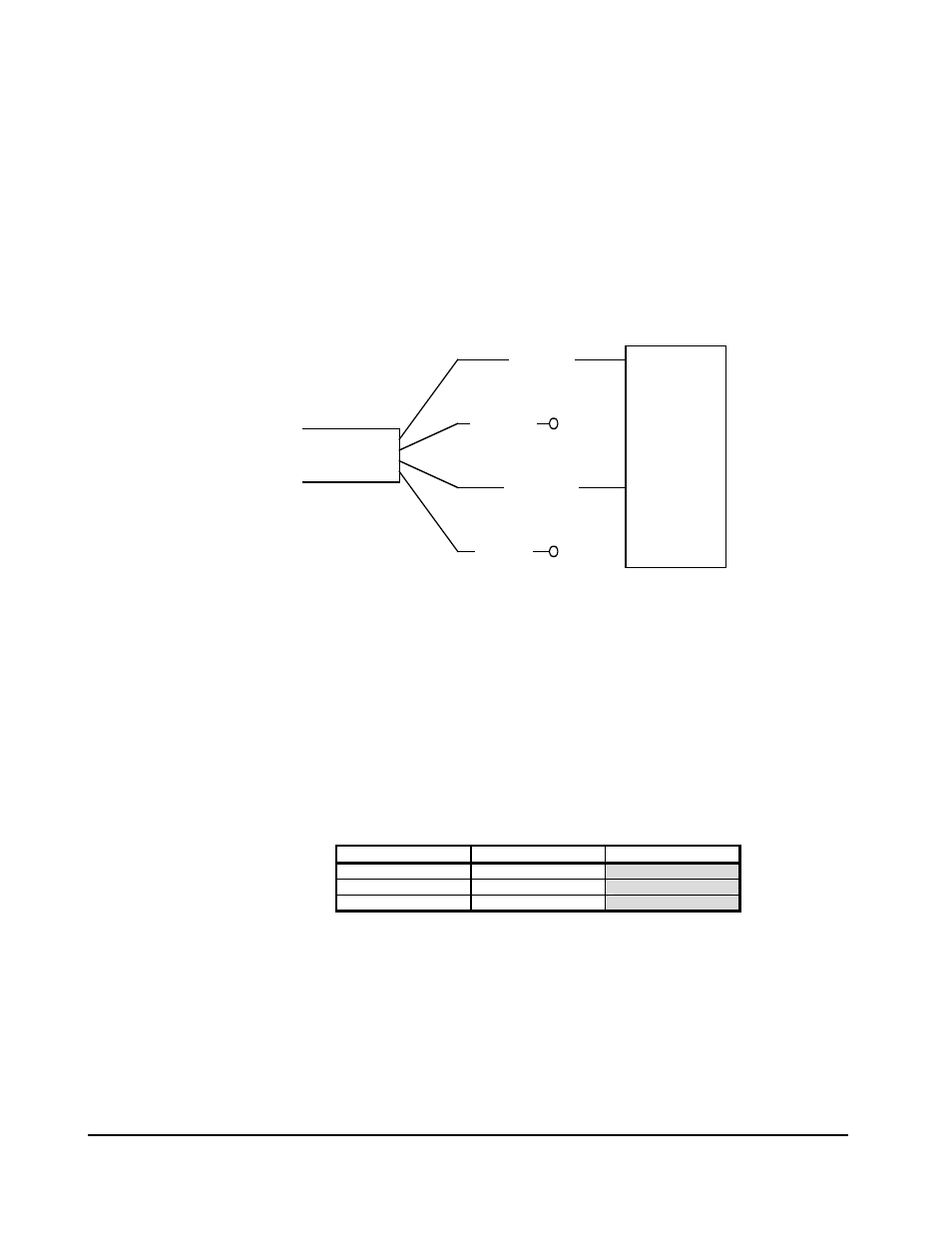
Differential Output Measurements
In a differential calibration, each channel of the SMU-9000 is
calibrated individually. After calibrating each channel, a
“balanced to ground” output is taken from the two the positive
labeled output wires in order to display the differential output
voltage. To accomplish this, connect the positive output wires to a
voltmeter as shown in Figure 10.
DVM
P/O CABLE
WHITE CH A +
BLUE CH B -
ORANGE CH B +
GREEN CH A -
+ INPUT
NC
NC
- INPUT
Figure 10. Differential output wire connections
This “balanced ground” connection allows the output of one
channel to be subtracted from the other, producing a differential
voltage reading at the voltmeter. For example, the differential
output voltage measurements of a system calibrated using this
method may look similar to the following:
Table 2. Differential Output Readings
Channel A Output
Channel B Output
Ch. A - Ch. B
0 V
+10 V
-10 V
+6.3 V
+6.3 V
0 V
+10 V
0 V
+10 V