Differential calibration – Kaman SMU9200 User Manual
Page 14
SMU-9000 User Manual
11
••••
Part III: Calibration
Interaction between the controls should decrease with each
iteration. To calibrate the system:
1.
Position the target at the minimum displacement from the
sensor (offset distance). Adjust the “Zero” control until the
system output voltage reads zero or the minimum output
voltage desired.
2.
Position the target at the maximum displacement from the
sensor (offset distance plus full range). Adjust the “Gain”
control until the system output voltage reads the maximum
output voltage desired.
3.
Repeat steps 1 and 2 until the system output is calibrated.
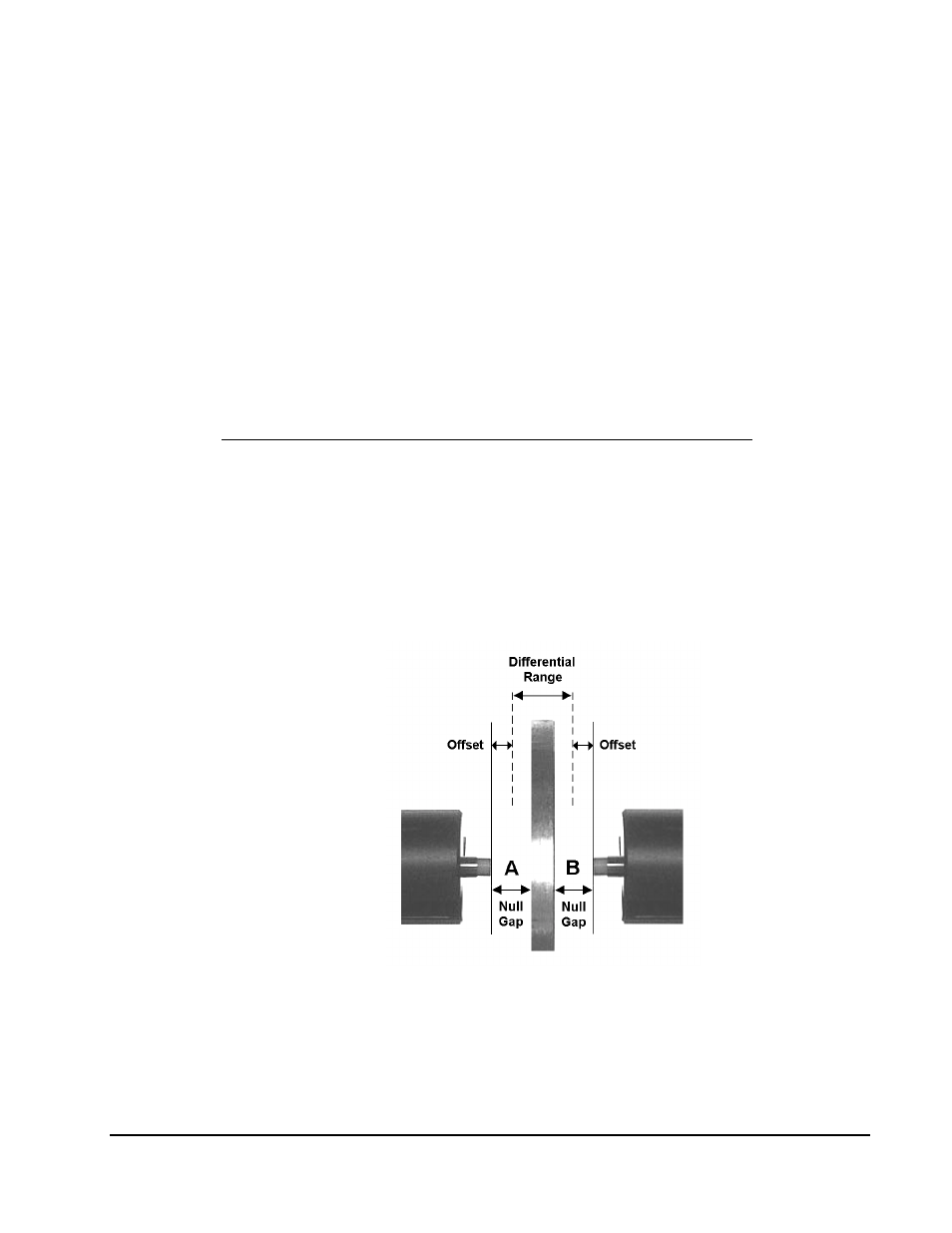
Differential Calibration
Although the SMU-9000 does not offer a true differential output,
a differential calibration is still possible with two channel and four
channel systems. Sensor installation in this case is similar to that
of the single channel configuration with an offset region and
measurement range established for each sensor. An illustration of
a typical differential calibration setup is shown in Figure 9.
Figure 9. Differential Calibration Setup
With this type of calibration, the measurement range is shared by
two sensors and is referred to as the differential range. For
example, when one sensor is positioned at maximum displacement