3 bipolar voltage output calibration procedure – Kaman KD-2306 User Manual
Page 12
Kaman Precision Products
PART NO: 860512-001
www.kamansensors.com
Last Revised: 8/3/2009
12
4
Reposition the target to minimum displacement (i.e. offset). Adjust the MIN (Zero) controls
until the output is 4 mA.
5
Reposition the target to mid-scale plus offset and adjust the MID (Gain) controls until the
output voltage reads 12 mA.
6
Reposition the target to full-scale displacement, plus offset. Read the current output and note
the difference between the actual reading and the desired reading. Adjust the MAX
(Linearity) controls until the output reads the desired 20 mA.
NOTE: The oversetting technique described in previous sections may not work with the 4-20
mA output due to lack of “headroom” above 20 mA.
7
Repeat Steps 4 through 6 as many times as necessary until the desired output at each point
is obtained without additional adjustment.
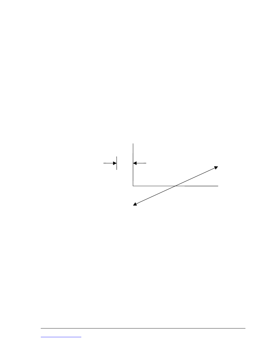
4.3.3 Bipolar Voltage Output Calibration Procedure
When you use this calibration procedure, output voltage will range from a negative voltage for the first
half of your measuring range to a positive output for the second half of the range.
VDC
offset
DISPLACEMENT
Bipolar Output Calibration
Use this method when your application requires a positive and negative output deviation from some
nominal value, in this case, 0 VDC. Bipolar calibration also provides maximum output sensitivity. (An
alternate technique is listed in the next section that will provide bipolar output, but not maximum
sensitivity).
In a bipolar calibration, clockwise rotation of the MIN (Zero) controls cause output to go more positive;
whereas, clockwise rotation of the MID (Gain) controls increases gain more negatively in the lower
half of the range and more positively in the upper half. Because of this, you will adjust the MID (Gain)
controls when the target is closest to the sensor and adjust the MIN (Zero) controls at the mid-scale
position.
1. Install the sensor in the calibration or application fixture at the offset distance.
2. Position the target using the micrometer fixture or spacers so that the total distance between
the sensor and target is equal to the specified full-scale displacement for that sensor, plus
offset.
3. Adjust the MAX (Linearity) controls until the output is equal to the desired full-scale reading.
4. Reposition the target so that it is at mid-scale (plus offset) and adjust the MIN (Zero) controls
until the output reads zero.