3 calibration procedures, 1 full scale calibration procedure (voltage) – Kaman KD-2306 User Manual
Page 10
Kaman Precision Products
PART NO: 860512-001
www.kamansensors.com
Last Revised: 8/3/2009
10
4.3 Calibration Procedures
Here are some general comments that are applicable to all calibration produces:
1. Mechanical positioning of the sensor must be performed accurately using a calibrated
micrometer fixture, precision spacers, or other dimensional standard.
2. A sample of the actual material to be measured by the system must be used as a calibration
target. Conductivity of the measured material affects system performance.
3. An inductive sensor always has an offset between the sensor face and start of its measuring
range. The offset serves two purposes a) It prevents mechanical damage caused by the
target striking the sensor face. b) It removes a very non-linear part of sensor output from the
measuring range making calibration easier, and performance much more linear. In general,
the offset is approximately 10 – 20% of the specified range.
4. Select the calibration procedure that is best for the application. Select the proper offset
distance, full-scale range, and desired voltage output. Calculate the midscale range and
output.
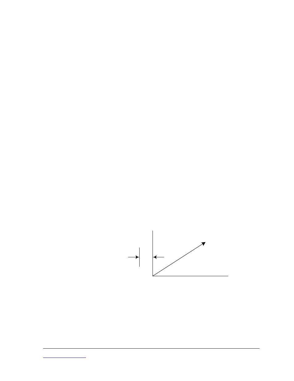
4.3.1 Full Scale Calibration Procedure (Voltage)
Full-scale calibration produces an output voltage that varies from 0 Vdc when the target is closest to
the sensor (plus offset) to some maximum positive voltage when the target is farthest from the
sensor.
For Single-Ended Output, monitor the voltage between terminals 1 & 3. Note that for the Single-
Ended Output, terminal 3 is GND
For Differential Output, monitor the voltage between terminals 1 & 5. Both terminals 1 & 5 contain
voltage and cannot be grounded without causing erroneous readings and possible system failure.
DISPLACEMENT
offset
VDC
0
Full Scale Calibration
1. Install the sensor in the calibration or application fixture at the offset distance from the target.
2. Position the target using the micrometer fixture or spacers so that the total distance between
the sensor and target is equal to the specified full-scale displacement for that sensor, plus
offset.
3. Adjust the MID (Gain) controls so that system output equals the desired full-scale output
voltage.