Dwyer 295 User Manual
Page 7
KP
1-3. Adjustment method and procedure same as dEAdzone.
4. Push
5. Push
6. Adjust KP values with
without additional operation. Users can easily check its adjustment by changing the
current input signal to the positioner. Optimum control value is found by adjusting
values during valve operation.
7. Push
8. Push
9. Push
PT
1-3. Adjustment method and procedure same as dEAdZONE.
4. Push
5. Push
6. Adjust PT value with
without additional operation. Users can easily check its adjustment by changing the
current input signal to the positioner. Optimum control value is found by adjusting
the values during valve operation. Push
message appears on LCD.
7. Push
8. Push
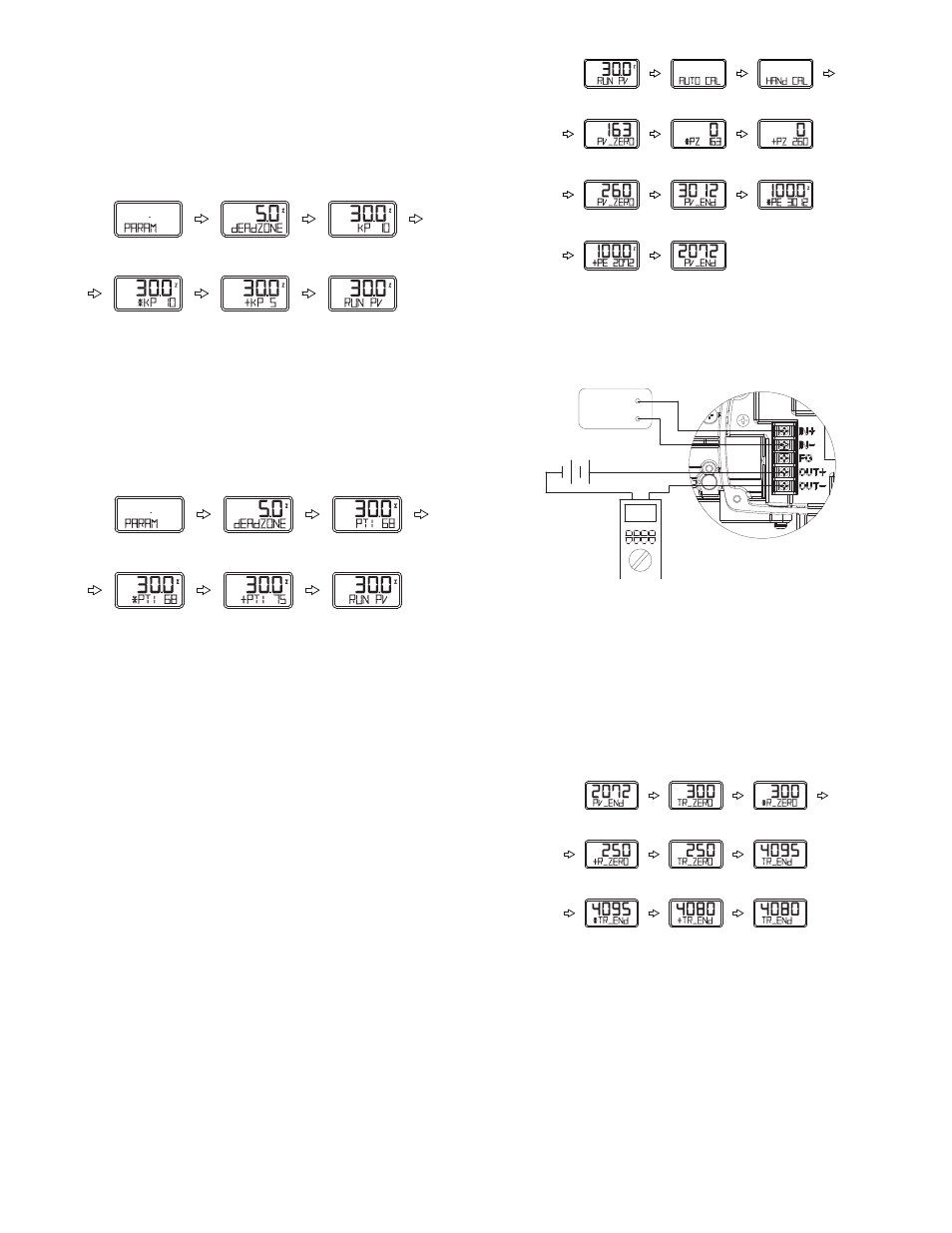
HAND CAL
When auto calibration is started, Series 195 and 295 positioners set zero points
and end points based on full stroke.
Hand Calibration Types
PV_ZERO: Edit mode to change the zero point of valve.
PV_END: Edit mode to change the end point of a valve.
TR_ZERO: Edit mode to change the zero point of transmitter.
TR_END: Edit mode to change the end point of transmitter.
Adjustment of valve zero point (1 to 5) and end point (6 to 10).
1. Push
displayed. Push
2. Push
3. Push
available to change valve zero point, and the valve stem moves automatically to the
current zero point. On LCD, the valve stroke is displayed as 0%. +PZ message that
indicates edit mode of zero point and inner value showing current zero point
position is also displayed.
4. Adjust valve stem by pushing
at the desirable zero point, save it with
5. Push
mode.)
6. In order to change valve end point, push
PV_END mode begins.
7. Push
available to change valve end point, and the valve stem moves automatically to
current end point. On LCD, the valve stroke is displayed 100%. *PE message
indicating edit mode of end point and inner value of end point is also displayed.
8. Adjust valve stem with using
desirable end point, save it with
9. Push
10. Push
Adjustment of zero point (1 to 4) and end point (5 to 9) of transmitter.
If valve zero point and end point are changed, transmitter is also changed
automatically. Usually there is no need for the transmitter zero point and end point
to be adjusted by users, but if transmitter output signal is unstable, transmitter zero
point and end point should be adjusted. The ammeter showing feedback signal is
necessary and the connection should be down as shown.
1. Push
2. Push
the zero point of the transmitter. Valve stem is moved to zero point automatically.
3. Push
current value is changed accordingly on an ammeter equipped outside. Adjust it to
be 4 mA and push
4. Push
5. Push
6. Push
the end point of the transmitter. The valve stem is moved to the end point
automatically.
7. Adjust measured current value to be 20 mA on ammeter with
buttons. Push
8. Push
Feed back signal
(12 ~ 30V)
4 ~ 20 mA
INPUT
Page 7
3 times
then
3 times
COMPLETED
7 times
then
3 times
COMPLETED
6 seconds
3 times
then
then
COMPLETED
then
then
COMPLETED