Dwyer 265ER User Manual
Page 2
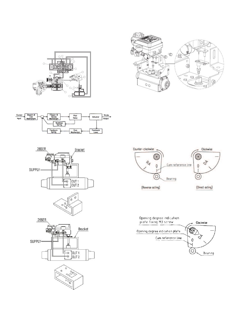
PRINCIPLE OF OPERATION
Increase the input current signal to change in lift position of valve. Force exerted
by (1) Torque Motor reduces Nozzle Back Pressure with increase in gap between
(2) Flapper and (3) Nozzle. Then (5) Spool moves upward and the (7) Seat opens
simultaneously. Air pressure of OUT1 pipe is discharged to (10) Actuator. As
pressure in the actuator chamber goes up, (12) Actuator Stem starts to rotate.
The movement of (12) Actuator Stem exerted force to the (a) Feedback Spring
through Feedback Shaft connections. Then (10) Actuator will stop at the point of
force balance exerted by the input current signal and the feedback spring.
BLOCK DIAGRAM OF 265ER
INSTALLATION
Example of attaching to actuator
Connection with Feedback Shaft
Attach to the position at which the positioner feedback shaft and the rotary
actuator main shaft are almost concentric (range in which the spring pin of
feedback shaft edge enters the hole of fork lever assembly shaft edge).
INSTALLATION cont.
Cam Attaching Procedure
Use the DA face of cam to turn the actuator main shaft clockwise (viewed from
the positioner front cover side) at the time of input feedback shaft. Use the RA
face to turn it counter-clockwise (reverse action). Correctly attach the cam to the
flange part of feedback shaft. Attach the cam in the procedure of loosening the
hexagonal nut with flange first, setting the using actuator to the starting position
and then setting the cam reference line and the bearing contact point of span
adjusting arm unit to the matching position. Do not apply the supply pressure
when attaching the cam as other wise it is very dangerous. When the positioner
is shipped out of our plant, the cam is tentatively tightened to the shaft. Be sure
to firmly lock the cam to the lock nut [tightening torque 17.7 to 22.1 in-lbs (2.0 to
2.5 Nm)].
Attaching Procedure of Opening Degree Indication Plate
Lock the cam and then adjust the zero point and span. Then fix the opening
degree indication plate to the shaft using the M3 screw provided. At the time, set
the opening degree indication plate to the state of attaching reference line.
SPA
RE
INPUT SIGNAL
4~20 mA
OUT2 OUT1
SUPPLY
OUT2
OUT1
OUT2
OUT1
1
2
3
4
5
6
7
8
9
10
11
12
13
14
15
15
E