Dwyer 2800 User Manual
Page 3
Reverse Acting Calibration
When calibrated to operate in the reverse acting mode the minimum
input signal produces the maximum output pressure and increasing the
input signal results in decreasing the output pressure. Setting the unit to
operate in the reverse acting mode is accomplished by positioning
internal electrical switches.
Disconnect input signal and supply pressure. Take off the top cover by
removing the four screws.
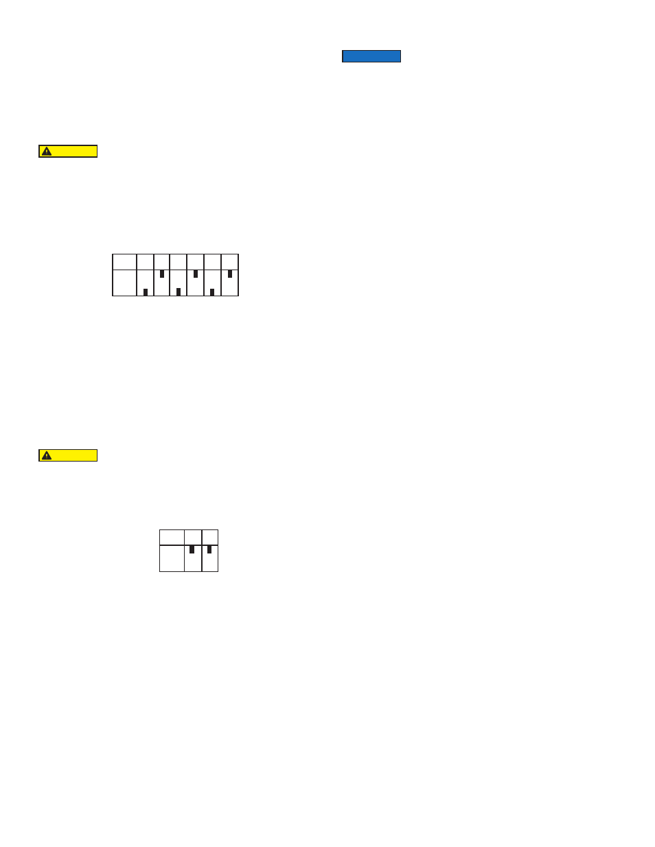
Position switches as illustrated in figure 4. Replace cover. Set the input
signal to the minimum value being used. Turn the zero screw to set the
maximum output pressure. Set the span by applying the maximum input
signal. Turn the span screw to set the minimum output pressure. It may
be necessary to repeat steps above until both end points are at desired
values.
Split Range
When calibrated to operate in the split range mode, a full input signal (i.e.
4-20 mA) will operate the unit at one half the normal output span (i.e. 3-
9 psig, 9-15 psig). Setting the unit to operate in the split range mode is
accomplished by positioning internal electrical switches. Disconnect
input signal and supply pressure. Take off the top cover of the unit by
removing the four screws.
Position switches as illustrated in figure 5. Replace cover. After setting
switches, refer to the appropriate calibration procedure (Direct Acting or
Reverse Acting) to get to desired output range (i.e. 3-9 psig, 9-15 psig).
MAINTENANCE
Cleaning
If clean, dry air is not used the orifice can become blocked. To clean, first
turn off supply air, then remove the screw located under the zero
adjustment. Unplug the orifice by using a wire that has a smaller
diameter than 0.012˝ (0.30mm). Use compressed air to blow out any
loose particles inside the orifice screw assembly.
Precautions
The bonnet should be removed only if a different operation mode is
desired which requires a change in circuit board switch settings. In this
case, precautions are necessary.
Never handle circuit board unless properly grounded to prevent ESD
(Electro-static Discharge).
If ESD grounding equipment is not available, hold the 2800 by its
castings and adjust switches using a non-conductive device such as a
pencil or a small rubber handled screwdriver.
Never remove circuit board for any reason. This will shift other
components and possibly damage the pressure sensor, both cases
resulting in malfunction.
Use caution when replacing bonnet. If any resistance is felt, remove
bonnet and determine the interference. Typically it will be the strain relief
grommet on the wires. The grommet should be oriented so it sits beside
the switches.
Clean and dry air should be used with the 2800. Foreign matter in the
supply line can clog the orifice openings. (.013˝ for a 3-15 psig unit,
smaller for higher range unit.) Foreign matter can also collect on the
actuator causing erratic operation. Moisture in the supply line can
damage circuit board components.
The electrical specifications as outlined in these instructions must be
complied to. If more than one 2800 unit is driven by the same PLC, there
must be a minimum of 9.5 VDC available to each unit.
If difficulty is experienced during calibration or if turning the zero or span
screw has no effect on the unit, a resetting technique can be taken. Turn
both the zero and span screw a minimum of 30 revolutions in one
direction. Then turn both screws exactly 15 revolutions in the opposite
direction. This procedure will put the potentiometers at their midpoint of
effective adjustability. Next, calibrate to desired settings starting with the
zero screw.
Reverse Acting Mode: For reverse acting units, the zero adjustment
refers to the minimum electrical signal and maximum output pressure.
The span refers to the maximum signal and the minimum output
pressure. For calibration in reverse mode the resetting technique can be
taken if necessary and calibration should always begin with the zero
screw.
Figure 4
Position of Switches for Reverse Acting Operation
Note: Switches not shown match Direct Acting Setting
(see Figure 3)
Figure 5
Position of Switches for Split Range Operation
Note: Switches not shown match Direct Acting Settings
(see Figure 3)
Switch
3
4
5
6
7
10
ON
OFF
Switch
1
2
ON
OFF
Signal
4-20 mA
Do not reverse the input leads. Avoid touching circuit board.
Shorting possible.
CAUTION
Avoid touching circuit board. Shorting possible.
CAUTION
Under normal circumstances, no maintenance should be
required.
NOTICE