Dwyer AFH2 User Manual
Page 4
Page 4
Connecting the Digital Manometer
1. Attach the instrument to the steel plate.
2. Connect the blue hose to the Reference port on the instrument.
Connect the clear hose to the Signal In port on the instrument.
2.3 Disassembly
Disassembly is essentially the reverse of the assembly procedure.
Disconnecting the Instrument
1. Disconnect the hoses from the digital manometer.
2. Detach the manometer from the metal plate.
3. Collapse the capture hood.
4. Store the instrument and components in the travel case.
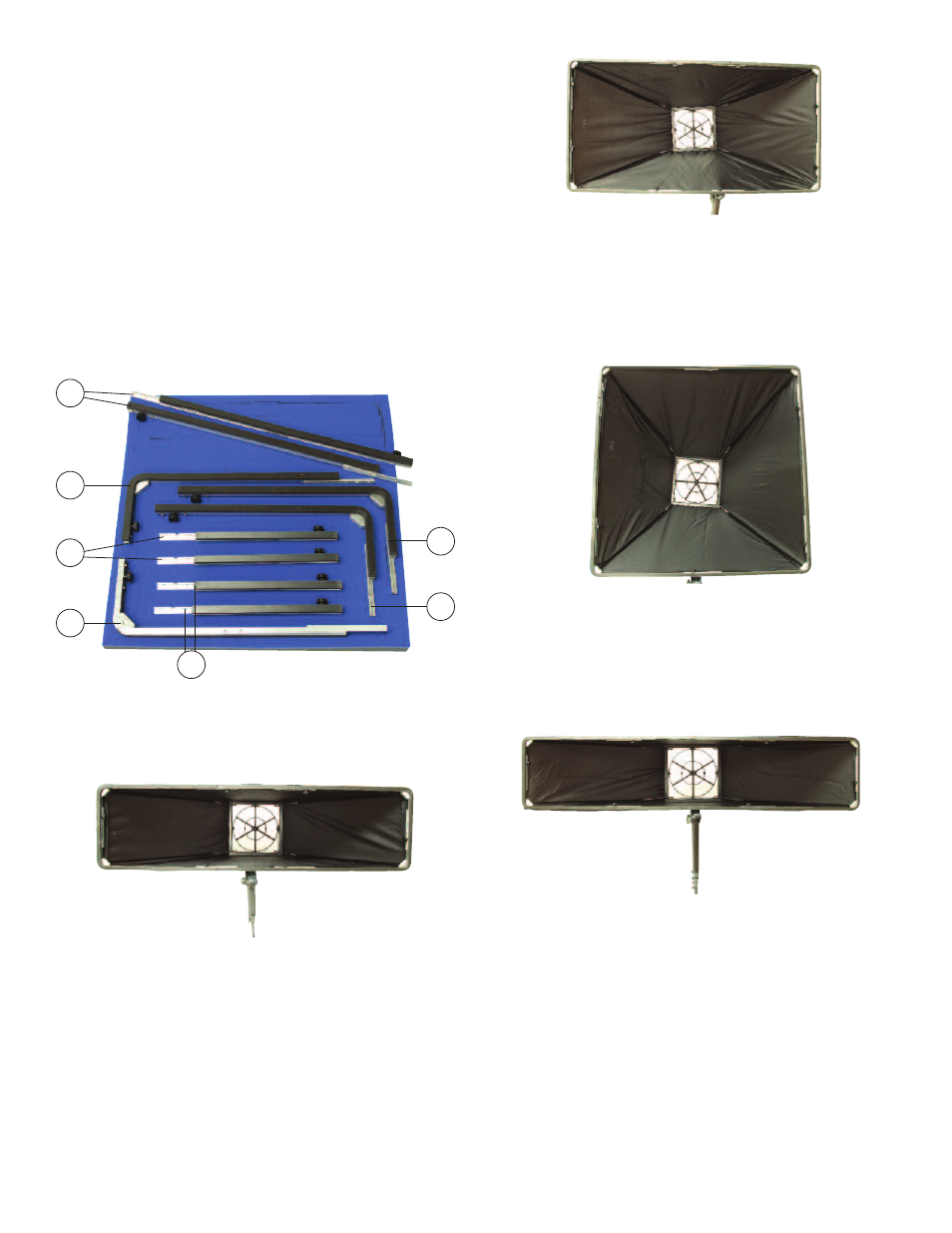
ASSEMBlING OPTIONAl FRAMES
The frames are fitted together using nuts. Each frame consists of the
corner pieces 1, 2, 3, and 4 and additional pieces can be inserted
between these to create different sized frames.
1 x 4’ (300 x 1200 mm) Canvas Model A-176
Use Parts 1 + 2 + 3 + 4 + A + A from A-175 Hood Adapter Kit.
Fit one A piece between pieces 1 and 2 and the other between pieces 3
and 4, then join piece 1 to piece 4 and piece 2 to piece 3. Attach the
smaller end of the 1 x 4’ (300 x 1200 mm) hood to the base and slot the
larger end into the channels in the frame ensuring that the canvas is not
caught. Fit the poles so that they run parallel to the side seams as shown
in picture.
2 x 4’ (600 x 1200 mm) Canvas Model A-177
Use Parts 1 + 2 + 3 + 4 + A + A + C + C from A-175 Hood Adapter Kit.
Fit one A piece between pieces 1 and 2 and the other between pieces 3
and 4, then fit one C piece between pieces 2 and 3 and the other
between pieces 1 and 4. Attach the smaller end of the 2 x 4’ (600 x 1200
mm) hood to the base and slot the larger end into the channels in the
frame ensuring that the canvas is not caught. Fit the poles so that they
run parallel to the side seams as shown in picture.
3 x 3’ (900 x 900 mm) Canvas Model A-179
Use Parts 1 + 2 + 3 + 4 + B + B from A-175 Adapter Kit.
Fit one B piece between pieces 2 and 3 and the other between pieces 1
and 4, then fit piece 1 to piece 2 and piece 3 to piece 4. Attach the
smaller end of the 3 x 3’ (900 x 900 mm) hood to the base and slot the
larger end into the channels in the frame ensuring that the canvas is not
caught. Fit the poles so that they run parallel to the side seams as shown
in picture.
1 x 5’ (300 x 1500 mm) Canvas Model A-178
Use Parts 1 + 2 + 3 + 4 + B + B from A-175 Hood Adapter Kit.
Fit one B piece between pieces 1 and 2 and the other between pieces 3
and 4, then join piece 1 to piece 4 and piece 2 to piece 3. Attach the
smaller end of the 1 x 5’ (300 x 1500 mm) hood to the base and slot the
larger end into the channels in the frame ensuring that the canvas is not
caught. Fit the poles so that they run parallel to the side seams as shown
in picture.
Optional hoods: 1 x 4’ (300 x 1200 mm), 2 x 4’ (600 x 1200 mm),
1 x 5’ (300 x 1500 mm), 3 x 3’ (900 x 900 mm)
1
B
3
4
2
C
A
Assembling A-174 low Flow Hood
Adapter plate A, 15.7˝ x 15.7˝ canvas and four (4) extension poles are
used to assemble the low flow hood. The adapter plate is placed on top
of the sensor grid beneath the brass fittings.
To remove: Gently pull until the adapter plate slides out of place.
To replace: Slot the adapter plate underneath the brass fittings on
one side of the grid and push gently until it slots beneath the second
pair of brass fittings.