Dwyer AFH2 User Manual
Page 3
SPECIFICATIONS
Service: Air.
Volume Flow Rate Units: CFM, l/s, m
3
/hr.
Volume Flow Ranges:
Supply: CFM: 41 to 1176; l/s: 19 to 555; m
3
/hr: 69 to 2000;
Exhaust: CFM: 45 to 1176; l/s: 21 to 555; m
3
/hr: 76 to 2000.
Volume Flow Ranges with low Flow Kit:
Supply: CFM: 25 to 1176; l/s: 12 to 555; m
3
/hr: 43 to 2000;
Exhaust: CFM: 29 to 1176; l/s: 14 to 555; m
3
/hr: 49 to 2000.
Accuracy @ 20°C (68°F):
Supply: ±3% of reading ±9 CFM (±4 l/s, 14 m
3
/hr);
Exhaust: ±3% of reading ±9 CFM (±4 l/s, 14 m
3
/hr).
Span Stability v. Temperature: Better than 0.1% of range in use per
2°F (1°C).
Zero System Accuracy: ±1 count (±0.05 Pascal typical; ±0.0002 in
w.c.).
Temperature limits:
Operating: 32 to 122°F (0 to 50°C);
Storage: 23 to 122°F (-5 to 50°C).
Thermal Effect: ±0.1% of range in use per 2°F (1°C).
Zero Drift: Negligible due to auto zero system. When auto zero set at
30 second intervals (2 minute warm up).
Orientation Effect: Any 45 degree change 0.0004 in w.c. (0.1 pascal)
typical.
System Air leak: 0.366 in
3
/hr (0.1 ml/min) @ 20 in w.c. (5 kPa)
typical.
Maximum Differential Pressure: 60 in w.c. (15 kPa).
Auto Ranging Display: 0.375˝ high digits.
Resolution: 1 CFM, 1 l/s, 1 m
3
/hr.
Output: RS-232 serial interface (baud rate 9600).
Memory Capability: 2500 readings in any engineering unit.
Power Requirements: 8.4 V NiMH battery, installed functional, user
replaceable (optional 9 V alkaline battery may be used in place of
rechargeable).
Dimensions: 30˝ x 24˝ x 24˝ (965 x 610 x 610 mm). Hood only: 2´ x 2´
(600 mm x 600 mm).
Weight: 8.8 lb (4 kg).
Agency Approval: CE.
SECTION 2: DESCRIPTION
2.1 Power Supply
The manometer is powered by one 9V battery or equivalent. The battery
is contained in the battery compartment, which is accessible by
removing the clip-on cover on the back of the digital manometer.
To conserve battery power, the instrument has an AUTO-OFF feature
that may be turned on or off. If you wish to learn how to use this feature
of the digital manometer, please see page 6 (Setting the Switch Off
Period).
2.1.1 Battery Selection: 9 volt or equivalent battery.
2.1.2 Installing the Battery
1. Remove the manometer from its rubber casing.
2. Remove the battery compartment cover by pressing and sliding in the
direction of the arrow.
3. Insert the proper 9V connection to the top of the battery in the correct
orientation.
4. Replace the battery compartment cover and ensure it is clipped in
place.
5. Place the manometer back into its rubber holder.
2.2 Assembly
The nylon capture hood is extended and tensioned using 4 glass-fiber
stiffening poles placed between the molding and the hood frame. Note:
The degree of flexing required to fit the poles will vary with the hood.
Erecting the Hood
Note: Refer to the appropriate pole-arrangement diagram.
1. Remove the hood assembly from the carrying case and place on the
ground with the hood attachment upwards.
2. Remove the 4 stiffening poles from their packaging. Place them
somewhere accessible from a standing position.
3. Leaving the bellmouth on the ground, unfurl the hood and open.
Remove out of its hinged frame.
4. Holding the frame against your body with one hand on the opposite
side, insert the lower end of a pole into one of the poles already
attached to the corner of the bellmouth molding. Locate the upper end
of the pole into the hole at the opposite corner of the capture hood.
5. Repeat this process next for the diagonally opposite pole – flexing of
the poles may be necessary, depending on the hood. When these two
poles have been inserted the assembly will be more-or-less self
supporting on one side.
6. Repeat this process for the opposite side and the two remaining poles.
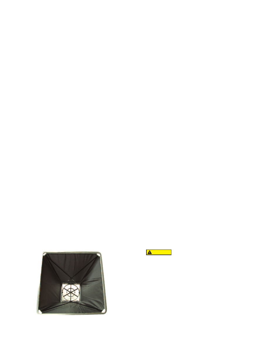
BASE UNIT WITH HOOD AND FRAME STRUCTURE
Assembly of 2 x 2’ (600 x 600 mm) Frame
Page 3
Hood Handles
Installation: Ensure that the base unit is clean and dry. Flip up the
latches on each handle. Apply the handles to the base unit. Flip
down the latches to secure the handles. Test each handle by pulling
gently on it, if there is any movement remove the handle and repeat
the installation process.
Removal: Flip up the latches on each handle. If necessary, slide a
finger under the suction pad to release the suction. DO NOT attempt
to remove the handles without releasing the latches as this could
cause damage.
Check the handles before use and contact Dwyer
Instruments, Inc. immediately if any components are missing or
damaged.
• Check before use that all components are securely fastened.
• DO NOT apply more than 45 kg of force to the handles.
• Dwyer Instruments, Inc. does not accept liability for any damage or
injury caused by improper use.
Positioning of Handles:
• Both handles can be fitted to the inside of the base.
• Both handles can be fitted to the outside of the base.
• One handle can be fitted to the inside and the other to the outside
of the base.
CAUTION