Optional relay – Dwyer LCR20 User Manual
Page 9
April, 2003 Page 9 of 20 LCR20 IOM
Optional
Relay
Connections
Relay
Pen 2
Relay Pen 1
Optional
Relay
J3
J1
J2
J5
P1
P2
1
2
3
4
T/C
(Connected to
power input)
P
en 1
P
en 2
J4
1
2
3
4
1
2
3
4
RTD
1
2
3
4
Voltage/
Current
1
2
3
4
Optional
Relay
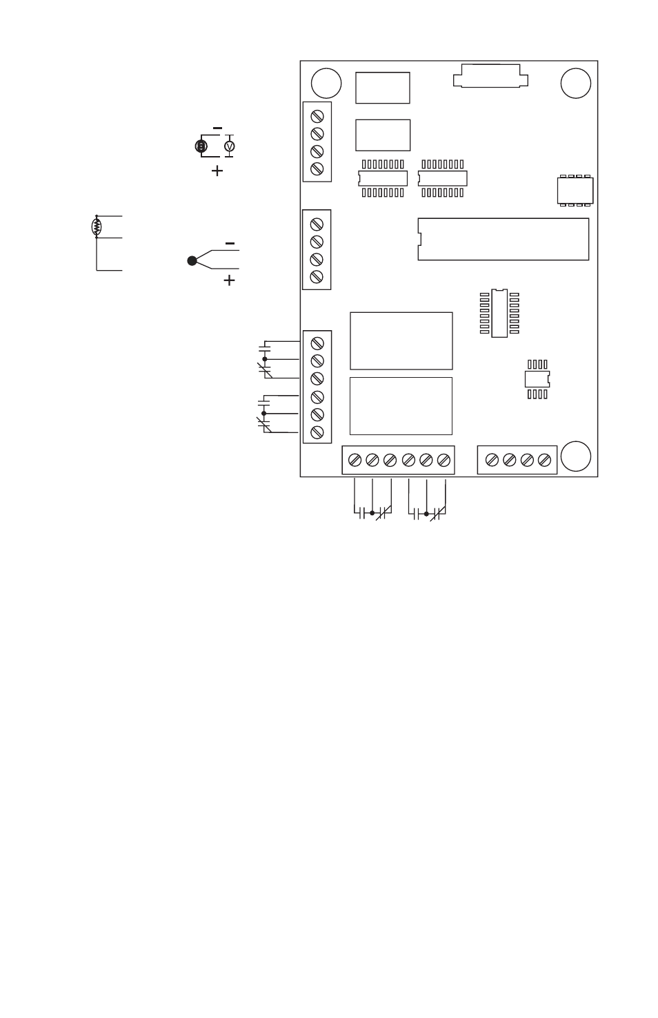
INPUT WIRING
PEN 1 / PEN 2
Figure 2-3 Input/Relay wiring - PCB layout
2-7 Thermocouple Input Wiring
Thermocouple input connections are shown in Figure 2-3. The correct
type of thermocouple extension lead-wire or compensating cable must
be used for the entire distance between the unit and the thermocouple,
ensuring that the correct polarity is observed throughout. Splices in the
cable should be avoided, if possible.
If the length of thermocouple plus the extension wire is too long, it may
affect the temperature measurement. A 400 ohms K type or a 500 ohms
J type thermocouple lead resistance will produce approximately 1 degree
C temperature error.
- DPMX (2 pages)
- DPMP-4 (2 pages)
- DPMP-5 (2 pages)
- DPML-4 (2 pages)
- DPML-5 (2 pages)
- DPMW (2 pages)
- MPM (36 pages)
- SPPM-HSG (1 page)
- SPPM (4 pages)
- SPPM-C (4 pages)
- A-SPPM-TC (2 pages)
- ULB (18 pages)
- CRF2 (4 pages)
- CLT (2 pages)
- PBLT2 (1 page)
- PBLTX (4 pages)
- SBLT2 (1 page)
- SBLTX (4 pages)
- MBLT (2 pages)
- FBLT (2 pages)
- ULT (8 pages)
- UTC (20 pages)
- ULTM (20 pages)
- ULSL (30 pages)
- 1500 (16 pages)
- 2600 (52 pages)
- 2500 (16 pages)
- 16A (1 page)
- 16A (44 pages)
- 1600 (8 pages)
- 1600 (36 pages)
- 8600 (40 pages)
- 8C (6 pages)
- 32B (32 pages)
- SCZ10 (20 pages)
- 8C (24 pages)
- 32A (36 pages)
- 32DZ (40 pages)
- SCD (10 pages)
- SCD-PS (2 pages)
- SCD-8 (2 pages)
- SCD-LED (2 pages)
- 650 (2 pages)
- 651 (2 pages)
- 659RTD (2 pages)