Dwyer DCT1000DC User Manual
Page 8
Still need help? Please feel free to contact one of our customer service representatives or visit us on the web at www.dwyer-inst.com. Thank
you for choosing Dwyer Instruments, Inc.
Printed U.S.A. 10/10
4.0 Glossary of Terms
• Run Mode: The term used when the timer board is firing the
solenoids.
• Pressure Module: The pressure measurement subsystem that
includes the software and hardware for on-demand cleaning, alarms
and signal retransmission of the process variable (i.e., the differential
pressure across the dust bags).
• Master Controller: The primary timer board that contains all of the
major features, connections for external inputs and power to drive the
DCT1000DC Dust Collector Timer Controller system.
• Power DC Guard: A plastic shield that covers the output triacs and
other line voltage circuitry.
• Demand Cycle Mode: A process in which the run mode is enabled
through the on-board pressure module or an external switch.
• Euro Connector: A “caged” connection used to terminate solenoids,
incoming power, or external switches on the DCT1000DC.
• Continuous Cycle Mode: A time based cycling mode dependent on
solenoid time on/off settings and time set between complete cycles.
• Manual Override: Allows the user to override the DCT1000DC
remotely or from the master controller panel through use of a switch or
a wire jumper.
• Slave Board: A channel expander that is used in conjunction with the
master controller to accommodate additional solenoids on larger dust
collection systems. It can be recognized easily as it does not have the
on-board display panel or the power supply present. A master
controller may also be used as a slave board.
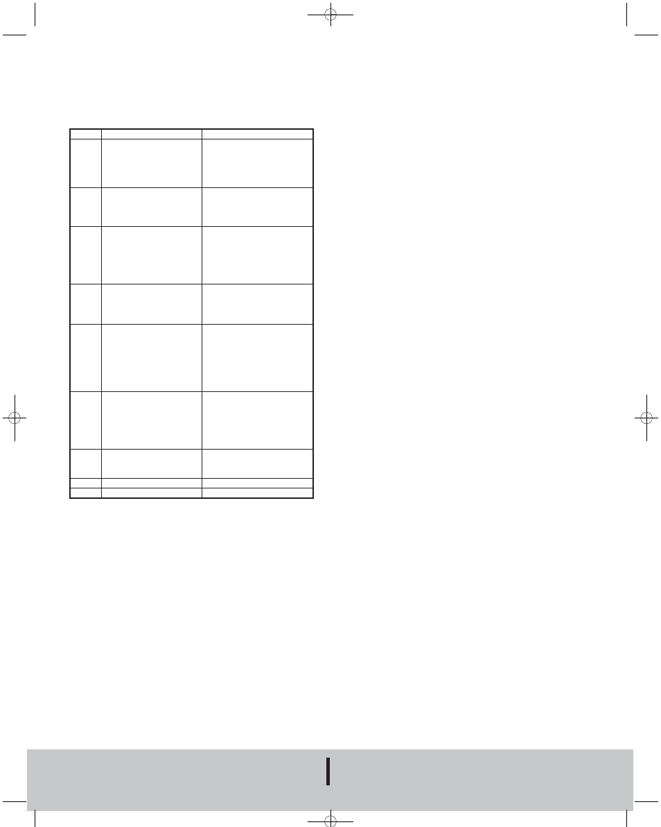
Meaning
This is a “watchdog” reset
that is enabled when the
master controller isn’t able
to cycle through its
operation.
The pressure module has
failed to respond to the
request of the master
controller.
Communication error in the
daisy chain interface. This
will only appear when the
master controller is used in
conjunction with a slave
board.
The master controller has
detected a change in
module configuration or a
fault in one of the modules.
If the fault described in “Err
4” is not corrected, the
master controller will
reconfigure the modules
that are responding
properly and operate at a
degraded condition.
A message error affecting
the software of the master
controller or one of its
modules.
Indicates that one of the
triac drivers are not
functioning.
Internal Error.
Unassigned message code.
Action Required
Make sure all electrical
connections are appropriately
shielded so the master
controller is not disrupted by
noise.
The master controller will try
to recover from the fault. If
unsuccessful, replace the
pressure module.
Make sure the control cable
used in the daisy chain
interface is properly shielded
from noise.
Reinstall all modules in
accordance with the
instructions in the factory IOM.
Reinstall all modules. Contact
factory if the problem persists.
Check the integrity of all
connecting cables used to
drive slave boards for
additional solenoids. Also
check the electrical grounding
of the system installation.
Return to factory for
evaluation and repair.
Contact the factory.
Contact the factory.
Display
Err 1
Err 2
Err 3
Err 4
Err 5
Err 6
Err 7
Err 8
Err 9
3.5 Error Codes
Error codes will be displayed on the three-digit display when certain faults
occur. Most of these indicators are associated with the daisy chain
communication, but certain error codes pertain to single board operation
also. These codes are:
FR# 443123-05 Rev. 3
©Copyright 2010 Dwyer Instruments, Inc.
DWYER INSTRUMENTS, INC.
P.O. BOX 373 • MICHIGAN CITY, INDIANA 46361 U.S.A.
Phone: 219/879-8000
www.dwyer-inst.com
Fax: 219/872-9057
e-mail: [email protected]
E-97DC:e-97DC 10/5/10 8:27 AM Page 8