Solenoids, Figure 2 wiring connections – Dwyer DCT1000DC User Manual
Page 4
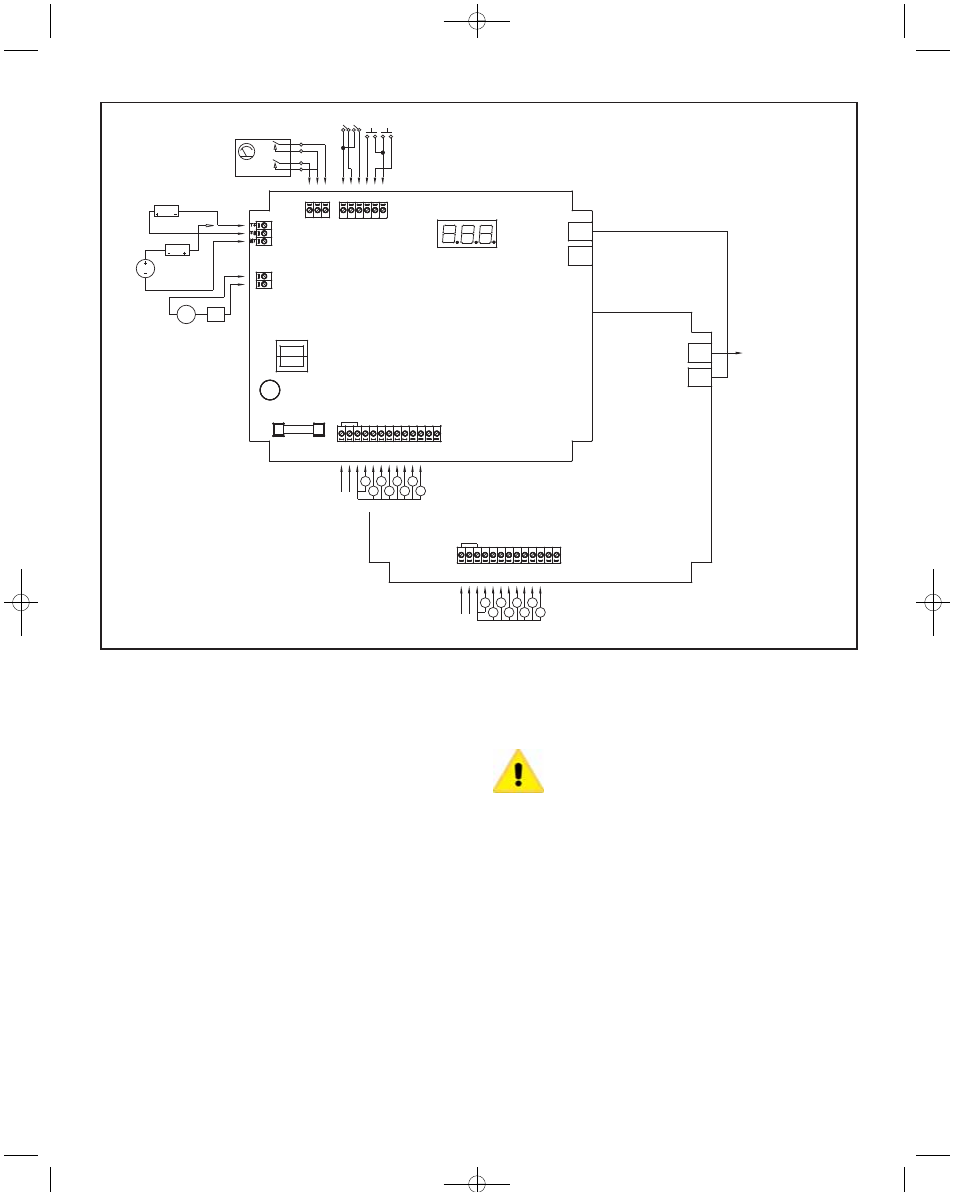
4-20 mA CONNECTIONS
LOW
LIMIT
HIGH
LIMIT
RECEIVER
USING DCT1000
24V SUPPLY
RECEIVER
SUPPLY
OPTIONAL
CONNECTION
USING EXTERNAL
POWER SUPPLY
4-20 MA
OUTPUT
TB4
4-20 MA
SOURCE
EXTERNAL
INTERNAL ALARM
CONT
ACTS
TB5
NORMALLY OPEN CONTRACTS
DCT1000DC
MASTER CONTROLLER
MASTER CONTROLLER
INPUT MUST NOT BE
CONNECTED
TO ADDITIONAL
EXPANDER MODULES
DCT1000DC
SLAVE BOARD
HIGH
LIMIT
LOW
LIMIT
COM
TB3
COM
ALARM
MODE
MAN
OVR
D1
CLN
ALARM
RESETCOM
DAISY
CHAIN
OUT
DAISY
CHAIN
IN
DAISY
CHAIN
OUT
DAISY
CHAIN
IN
(INTERNALLY CONNECTED)
TB1
L1
+
L2
-
SOL
COM
1
2
3
4
5
6
7
8
9
10
(10 CHANNEL SHOWN)
SOLENOIDS
LINE
INPUT
SOLENOIDS
LINE
INPUT
L1
+
L2
-
SOL
COM
1
2
3
4
5
6
7
8
9
10
(INTERNALLY CONNECTED)
TB1
(10 CHANNEL SHOWN)
F1
C3Ø4
SUPPLY
ALARM
LOAD
TB2
PRESSURE
LIMIT
SWITCHES
1.2.2 Manual Override Switch Connection
The manual override function allows the system to be set to the run mode
regardless of other conditions. This mode is enabled when the manual
override terminal and common are connected. It is disabled when they are
disconnected. If the controller is to be run in continuous mode, a jumper
wire may be wired across these terminals. When manual override is
needed on a periodic basis, wire a SPST toggle switch between the
manual override terminal and the common terminal.
1.2.3 Down Time Clean Connection
The down time clean operation forces the system into a run cycle for a
programmed length of time between 0 – 255 minutes. The operation is
initiated by connecting the down time clean terminal to a common
terminal. This function is best accomplished through use of an external
normally open switch.
1.2.4 Connecting Multiple Timer Boards
The DCT1000DC is available with up to 22 channels on single unit. Where
the installation requires more than 22 channels, the system may be
expanded up to 255 channels by daisy chaining multiple controller boards.
The system will automatically detect the total number of channels and
operate as a singel system.
To connect multiple boards together you will need one or more jumper
cables, Model DCA, available from Dwyer Instruments, Inc. in various
lengths. These are connected to the telephone-style connectors at the
upper right side of the controller boards. One board in the system is
designated as the master. Subsequent units become slave boards. The
master controller is the board at the head of the chain having no
connection to its daisy chain connector. Connect the cable from the daisy
chain out connector on connector on the master controller to the daisy
chain in connector of the first slave board. Subsequent slave boards are
connected from the daisy chain out connector on one board to the daisy
chain in on the next. The master controller must then be configured to the
system requirements. The display and status indicators of slave boards
are automatically disabled.
Caution: Do not use telephone jumper cables. These have
a “twist” in the connection and may damage the controllers.
Cables designed for use with the DCT1000DC are available
from Dwyer Instruments Inc.
1.2.5 Continuous Cycle Mode
The DCT1000DC has several operating modes available for different
applications. Starting with the most basic mode, it is capable of operating
in a continuous cleaning cycle. This can be initiated by either placing a
jumper between the high limit input and the common, or the manual
override input to the common connection. Controlling this cycle are three
setup parameters: time off, time on, and cycle delay. Time on and time off
specifically deal with the solenoid on time and the time interval between
the end of the on pulse and the start of the next. The cycle delay allows a
delay of up to 255 minutes to be programmed between the end of one
complete cleaning cycle and the beginning of the next. This allows
additional options for defining a cleaning profile.
1.4.3 Connecting the Alarm Relay
With the pressure module installed, a relay contact is provided for
controlling an external alarm. This relay is a single form-A contact. It is
activated when either the high alarm threshold is exceeded, or the
pressure drops below the low alarm threshold. The connection is made at
the two-pin connector TB5. See Figure 2 Wiring Connections
Figure 2
Wiring Connections
E-97DC:e-97DC 10/5/10 8:27 AM Page 4