Dwyer DCP200 User Manual
Page 2
3.0 Pressure Module Maintenance 4
1.0 Installation
Caution: Prior to installing the
DCP100A/200A please review the
operating specifications carefully.
Some operating systems, especially in
pneumatic conveying applications, may see
static pressure or vacuum conditions that
exceed the capability of the
DCP100A/200A pressure module. For
these conditions there are a number of
alternate Dwyer Instruments, Inc. pressure
products that can be used to meet your
application requirements, all of which can
be terminated to the Dwyer
®
DCT1000 Dust
Collector Timer Controller. For more infor-
mation on these and other Dwyer
®
prod-
ucts, please call us at (219) 879-8000, or
visit us on the web at www.dwyer-inst.com
or www.dust-controls.com.
1.1 Location
The system should be located in an enclo-
sure that meets relevant safety standards
and electrical codes. There are no other
special orientation requirements as the
pressure module is not orientation sensitive.
Care should be observed when routing the
air hoses to ensure that any potential con-
densation or moisture will not drain into the
sensor. Where heavy condensation is pre-
sent, a drip loop or an in-line filter should be
installed to ensure long term operation.
1.2 Connections
When a pressure module is installed, the 4-
20 mA process signal and the alarm relay
contacts are available. The circuit may be
used with the internal 24-volt power source
or with an external source. In either case,
the 4-20 mA circuit is isolated from ground
and other signals. The alarm relay contacts
are isolated, normally open contacts.
Pressure connections may be made to the
stepped hose barbs with either 1/8
″ or
3/16
″ I.D. tubing. The following subpara-
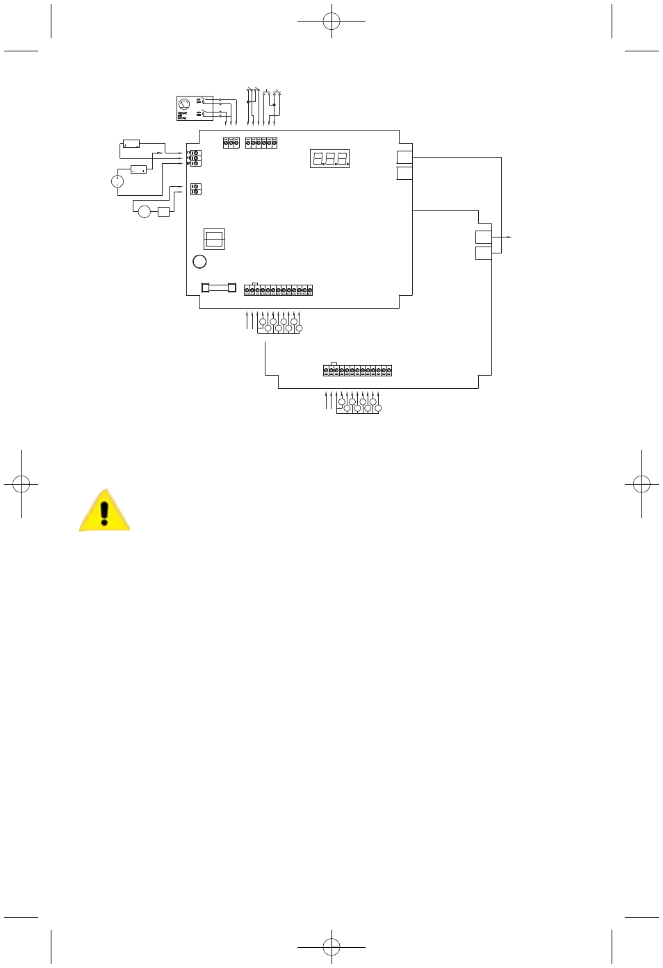
graphs describe the external switch con-
nections. Refer to Figure 1 (above) for
switch connection illustration.
1.3 Pressure Module Installation
The pressure module is attached to the
Master Controller using integral connectors
on both units. The insertion ports for the
pressure module are located in the upper
2
Fig. 1 - Switch
Connections
4-20 mA CONNECTIONS
RECEIVER
USING DCT1000
24V SUPPLY
RECEIVER
SUPPLY
OPTIONAL
CONNECTION
USING EXTERNAL
POWER SUPPLY
4-20 MA
OUTPUT
TB4
4-20 MA
SOURCE
EXTERNAL
INTERNAL ALARM
CONT
ACTS
TB5
NORMALLY OPEN CONTRACTS
MASTER CONTROLLER
MASTER CONTROLLER
INPUT MUST NOT BE
CONNECTED
TO ADDITIONAL
EXPANDER MODULES
SLAVE CHANNEL EXPANDER
HIGH
LIMIT
LOW
LIMIT
COM
TB3
COM
ALARM
MODE
MAN
OVR
D1
CLN
ALARM
RESETCOM
DAISY
CHAIN
OUT
DAISY
CHAIN
IN
DAISY
CHAIN
OUT
DAISY
CHAIN
IN
(INTERNALLY CONNECTED)
TB1
L1
L2
SOL
COM
1
2
3
4
5
6
7
8
9
10
(10 CHANNEL SHOWN)
SOLENOIDS
LINE
INPUT
SOLENOIDS
LINE
INPUT
L1
L2
SOL
COM
1
2
3
4
5
6
7
8
9
10
(INTERNALLY CONNECTED)
TB1
(10 CHANNEL SHOWN)
F1
C3Ø4
SUPPLY
ALARM
LOAD
TB2
E-97-M:dcp100/200module IOM-4/01 8/18/09 4:22 PM Page 2