Mercoid division – Dwyer DA-7035N User Manual
Page 4
MERCOID DIVISION
Phone: 219/879-8000
www.dwyer-inst.com
DWYER INSTRUMENTS, INC.
Fax: 219/872-9057
e-mail: [email protected]
P.O. BOX 258 • MICHIGAN CITY, INDIANA 46361, U.S.A.
©Copyright 1997 Dwyer Instruments, Inc.
Printed in U.S.A. 2/97
FR# 92-442122-00
LOCKING DEVICE
When the control has been adjusted to desired range, the locking bar may
be inserted between the adjustment screws with slot passing over the pro-
jecting lug. By placing a sealing wire between the locking bar and the hole
in the lug protruding from adjustment assembly, adjustments cannot be
tampered with.
For DAH and DSH, sealing wire may pass through locking bar and hole in
hub above adjusting knobs.
DAW, DRW, DSW, adjusting knob cover may be sealed in place with seal-
ing wire through cover bolt hole.
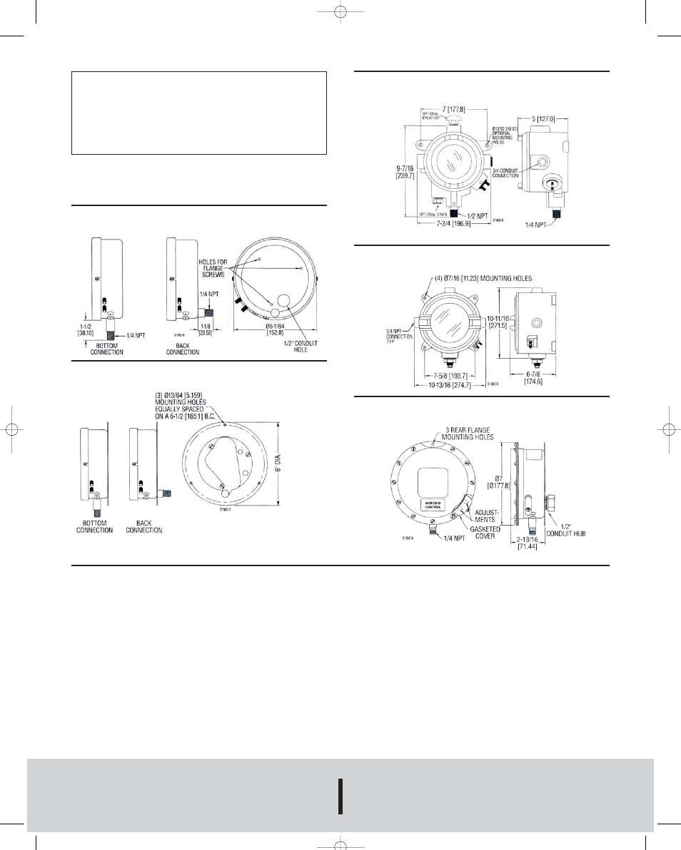
CONTROL DIMENSIONS
Note: Dimensional drawings shown are for general reference only.
Comprehensive drawings are available from factory upon request.
General Purpose
Types DA, DS, DR, DL
Drawing No. 1000B
Flange for Surface Mounting
Drawing No. 1000F
Explosion-Proof
Types DAH, DRH, DSH, DLH
Drawing No. 1350
Explosion-Proof
Types DAE, DRE, DSE, DLE
Drawing No. 98D
Weather-Proof
Types DAW, DSW, DRW, DLW
Drawing No. 1062
IN-526-N 8/30/05 2:06 PM Page 4