Da – ds – dr – Dwyer DA-7035N User Manual
Page 2
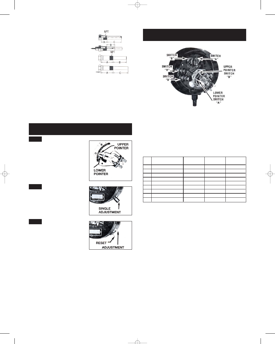
WIRING
Wire in accordance with local electrical codes or follow equipment manu-
facturer’s recommendations. On general purpose controls, do not attach
ridged conduit to case. use a short strip of BX to relieve conduit expansion
and contraction strains.
Where a control is connected directly into the load circuit, it must be con-
nected into the hot side of line.
Do not overload electrically - see nameplate attached to control for electri-
cal rating.
TWO-STAGE TEMPERATURE CONTROL
SERIES D-7435
TYPES DA-7435, DAW-7438, DAH-7435, DAE-7435 – This series incor-
porates two single pole, double throw snap switches, actuated by the
same Bourdon Tube. The operating point of each switch is adjustable
through an outside knob. The change in temperature which opens and
closes each switch at its respective setting is the “fixed differential” (sensi-
tivity) of the switch. The temperature represented by the difference
between the two adjustment points is the temperature “spread” between
operation of the two switches. Upper pointer indicates the operating point
of the “high” temperature circuit. Lower pointer indicates the operating
point of the “low” temperature circuit.
OPERATING RANGES/SERIES D-7435
With Snap-Action Contacts
ELECTRICAL RATING
AC capacities: 5A @ 120 V, 5A @ 240 V. (Not available for 440 V).
DC capacity: 5A, 30 V resistive.
Range
No.
1N
3N
4N
5N
7N
8N
9N
10N
11N
Scale Range
-60 to 30°F (-50 to 0°C)
0 to 100°F (-18 to 40°C)
50 to 150°F (10 to 65°C)
100 to 200°F (40 to 95°C)
140 to 300°F (60 to 150°C)
250 to 415°F (120 to 215°C)
350 to 550°F (175 to 290°C)
100 to 300°F (40 to 150°C)
100 to 500°F (40 to 260°C)
Max. Temperature
Not To Exceed
150°F (65°C)
240°F (115°C)
250°F (120°C)
300°F (150°C)
500°F (260°C)
550°F (290°C)
600°F (315°C)
500°F (260°C)
600°F (315°C)
Min. Spread
Between Switches
12°F (7°C)
13°F (8°C)
13°F (8°C)
12°F (7°C)
18°F (10°C)
18°F (10°C)
22°F (13°C)
22°F (13°C)
46°F (26°C)
Fixed Deadband
Each Switch
4°F (2°C)
4°F (2.5°C)
4°F (2.5°C)
4°F (2.5°C)
6.5°F (4°C)
7°F (4°C)
8°F (4.5°C)
8°F (4.5°C)
16°F (9°C)
ADJUSTMENTS
How to Set Operating Point of Control
DA –
DS –
DR –
Prefixed by DA, DAE, DAH, DAW –
Provided with double adjustments. Adjust
the upper pointer to set the “high” tem-
perature point for switch operation. Adjust
the lower pointer to set the “low” temper-
ature operating point. The difference
between the upper and lower pointers is
the operating differential between “on-off”
switch operation. Minimum differential for
each range is shown on Page 3.
Prefixed by DS, DSE, DSH, DSW –
Equipped with a single adjustment. The
single pointer on the scale sets the tem-
perature where switch operation occurs.
Differential is fixed (not adjustable). For
fixed differential of each respective range,
see Page 3.
DR-7035-153U. A single adjustment sets
the operating point for automatic opera-
tion. A push button reset must be operat-
ed manually to restore the circuit to the
original position after automatic operation.
Example – Type DR-7035-153L: circuit will
open automatically on a temperature rise
to the temperature indicated by the pointer
on the scale – no matter how much the temperature drops, the circuit will
not reclose until the reset button is operated.
Suffix -L denotes control will operate automatically on an increase.
Suffix -U denotes control will operate automatically on a decrease.
ILLUSTRATION
NO. 10
WELLS
Wells (with dimensions “A” and “C” in illus-
tration 10) are used to protect the remote
bulb from physical damage or to permit
removal of the bulb without draining the
system.
The use of a well will increase the time lag
of the control since the temperature
change of the controlled medium must be
transmitted through the wall of the well
and then the bulb. Thus when wells are
used, it is important that the well dimen-
sion “C” be greater than or equal to the
bulb length “B” to insure that all of the
temperature sensistive portion of the bulb
is within the liquid area.
DOUBLE ADJUSTMENT TYPES –
FULLY AUTOMATIC
SINGLE ADJUSTMENT TYPES –
FULLY AUTOMATIC
SEMI-AUTOMATIC CONTROL
WITH MANUAL RESET
IN-526-N 8/30/05 2:06 PM Page 2