Dwyer DA-7035N User Manual
Page 3
OPERATING RANGES/SERIES D-7000
With Snap-Action Contacts Types: DA-7035, DA-7235-153 & DA-7235-804
Adjustable
Operating
Range
-60 to 30°F (-50 to 0°C)
0 to 100°F (-18 to 40°C)
50 to 150°F (10 to 65°C)
100 to 200°F (40 to 95°C)
140 to 300°F (60 to 150°C)
250 to 415°F (120 to 215°C)
350 to 550°F (175 to 290°C)
100 to 300°F (40 to 150°C)
100 to 500°F (40 to 260°C)
ELECTRICAL RATINGS
Range
No.
1N
3N
4N
5N
7N
8N
9N
10N
11N
Max. Process
Temp. Not To
Exceed
150°F (65°C)
240°F (115°C)
250°F (120°C)
300°F (150°C)
500°F (260°C)
550°F (290°C)
600°F (315°C)
500°F (260°C)
600°F (315°C)
Minimum
Deadband
23°F (13°C)
25°F (14°C)
25°F (14°C)
25°F (14°C)
41°F (23°C)
42°F (23°C)
50°F (28°C)
50°F (28°C)
100°F (56°C)
See Code D
Fixed
Deadband
5°F (3°C)
5°F (3°C)
5°F (3°C)
5°F (3°C)
8°F (4.5°C)
9°F (5°C)
10°F (6°C)
10°F (6°C)
20°F (12°C)
See Code E
Fixed
Deadband
5°F (3°C)
5°F (3°C)
5°F (3°C)
5°F (3°C)
8°F (4.5°C)
9°F (5°C)
10°F (6°C)
10°F (6°C)
20°F (12°C)
See Code G
Bulb No./Cap. Mat’l.
No. 2 SS/Copper
No. 2 SS/Copper
No. 2 SS/Copper
No. 2 SS/Copper
No. 2 SS/Copper
No. 2 SS/SS
No. 2 SS/SS
No. 2 SS/Copper
No. 2 SS/SS
Bulb Min.
Insertion
Depth (2)
2-7/8˝ (73 mm)
2-7/8˝ (73 mm)
2-7/8˝ (73 mm)
2-7/8˝ (73 mm)
2-7/8˝ (73 mm)
2-7/8˝ (73 mm)
4-7/8˝ (124 mm)
2-7/8˝ (73 mm)
2-7/8˝ (73 mm)
Adjustable Deadband
Bulb Furnished With 6˝
Capillary Unless
Otherwise Specified (1)
Adjustable Deadband Fixed Deadband
DS-7235-804
(2) SPDT
DS-7235-153
DS-7035-153
Code
D
E
G
Circuit
Suffix No.
-153
-153
-804
120V
15A
15A
5A
240V
15A
15A
5A
440V
15@480V
NA
NA
120V
1/2A
ݘ
ݙ
240V
1/4A
ݘ
ݙ
AC
1/8
ݗ
NA
DC
NA
NA
NA
AC Capacity
DC Resistive
Horsepower
Circuit
Suffix No.
-153
-804
Switch Action
SPDT one circuit OPENS as other CLOSES
Two SPDT operate simultaneously in one direction upon increase
(or decrease when specified)
GENERAL BULB INFORMATION
All bulbs are made of 304 stainless steel; capillary material is either copper or 316 stainless steel, as shown in the range table. The maximum pressure of bulbs
with a process connection is 300 psi. Other bulbs are for non-pressurized (e.g., open tank) use only. Consult the factory for higher pressure applications.
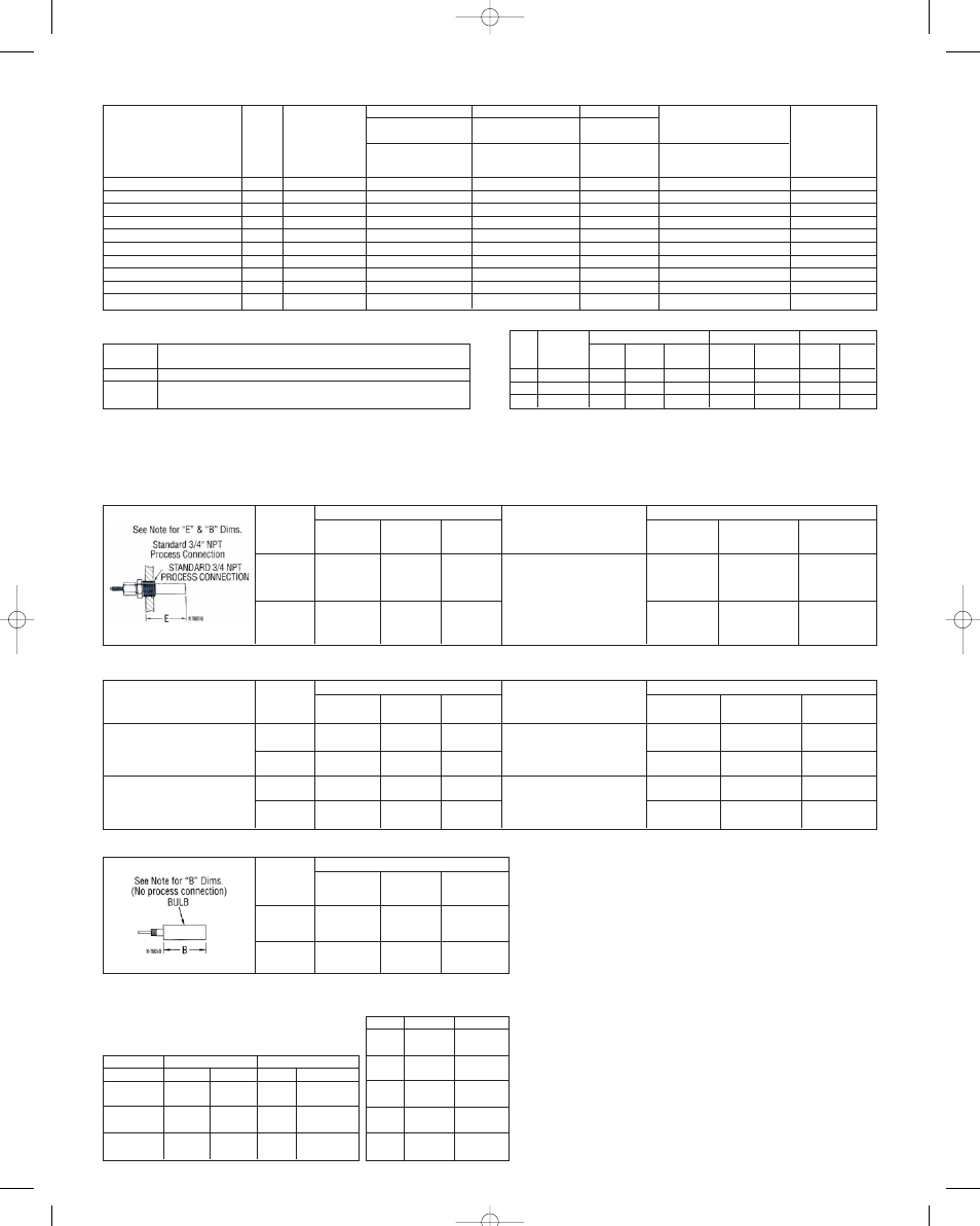
RANGE TABLE – NO. 2 BULB
Standard 11/16˝ Diameter Series D Bulb & 3/4˝ NPT Connection
RANGE TABLE – NO. 1 BULB
11/16˝ Diameter Series D Bulb for Open Tank Use
(1) All bulbs, including those with a copper capillary, are made or Type 304 Stainless Steel
(2) Insertion depth may be increased through use of bulb supports or wells.
Repeatability: ±1% of full scale.
ݗ 1/4 HP at 120V AC, 1/2 HP at 240V AC.
ݘ DC rated controls (up to 10A), consult factory.
ݙ 5A, 30V DC resistive.
Bulb (1)/
6 ft. Cap.
Tubing
SS Bulb/
Copper
Capillary
SS Bulb/
SS Cap.
1N, 3N, 4N,
5N, 7N, 10N
E=2-7/8˝
B=2-7/8˝
Standard
E=2-7/8˝
B=2-7/8˝
Option
8N, 11N
N.A.
E=2-7/8˝
B=2-7/8˝
Standard
9N
N.A.
E=4-7/8˝
B=4-7/8˝
Standard
Optional
11/16˝ Bulb
with
1/2˝ NPT
Process
Conn.
1N, 3N, 4N,
5N, 7N, 10N
E=3-1/2˝
B=2-7/8˝
E=3-1/2˝
B=2-7/8˝
8N, 11N
N.A.
E=3-1/2˝
B=2-7/8˝
9N
N.A.
E=5-1/2˝
B=4-7/8˝
Range Numbers
Range Numbers
Bulb (1)/
6 ft. Cap.
Tubing
SS Bulb/
Copper
SS Bulb/
SS Cap.
1N, 3N, 4N,
5N, 7N, 10N
B=2-7/8˝
Standard
B=2-7/8˝
Option
8N, 11N
N.A.
B=2-7/8˝
Standard
9N
N.A.
B=4-7/8˝
Standard
Range Numbers
Range
1N, 3N, 4N,
5N, 7N, 10N
8N, 11N
9N
E (Min.)
2-7/8˝
73 mm
2-7/8˝
73 mm
4-7/8˝
124 mm
C
3-1/4˝
83 mm
3-1/4˝
83 mm
5-1/4˝
134 mm
Brass
49-543
N/A
N/A
S.S.
49-251SS-1
49-251SS-1
49-253SS-1
Bulb Ass’y Well Dim.
Well Ass’y #
Temp.
70°F
(21°C)
200°F
(95°C)
300°F
(150°C)
400°F
(205°C)
550°F
(285°C)
Brass
1000 psi
6890 kPa
900 psi
6200 kPa
500 psi
3440 kPa
160 psi
1100 kPa
Do Not
Use
SS
2400 psi
16500 kPa
2250 psi
15500 kPa
2150 psi
14800 kPa
-
-
2000 psi
13700 kPa
CAUTIONS
Control movement must not be oiled.
Do not overload – note electrical rating on nameplate and be sure total current
passing through switch is within specified rating.
WARNING: A failure resulting in injury or damage may be caused by over-pres-
sures, excessive vibration or pressure pulsation, excessive temperature, corro-
sion of pressure containing parts and movement assembly, electrical overload,
or other misuse. Do not tamper with switch wires. Position of these wires is
essential to proper operation. Tampering with these wires will void warranty.
Protective Well Assemblies
For Series D. No. 2 Bulb, (Standard 11/16˝ Diameter)
Well Pressure Ratings
(1) All bulbs, including those with a copper capillary are made of Type 304 Stainless Steel
NOTES:
Dim. “E” = MINIMUM INSERTION DEPTH
Minimum clearance distance for bulb insertion: measured from the top outside
surface of female NPT.
Dim. “B” = ACTIVE BULB LENGTH
Length of bulb that responds to temperature change: measured from the free
end. Process fluid must have good contact with the bulb over this length.
RANGE TABLE – NO. 2 BULB
Optional 1/2˝ & 3/8˝ Diameter Bulbs with 3/4˝ NPT Connection
Range Numbers
1N, 3N, 4N,
5N, 7N, 10N
E=6-3/8˝
B=5-3/4˝
E=6-3/8˝
B=5-3/4˝
E=11-3/8˝
B=11-3/8˝
E=11-3/8˝
B=11-3/8˝
8N, 11N
N.A.
E=6-3/8˝
B=5-3/4˝
N.A.
E=11-3/8˝
B=11-3/8˝
9N
N.A.
E=10-5/8˝
B=10˝
N.A.
E=19-7/8˝
B=19-7/8˝
9N
N.A.
E=10˝
B=10˝
N.A.
E=19-7/8˝
B=19-7/8˝
8N, 11N
N.A.
E=5-3/4˝
B=5-3/4˝
N.A.
E=11-3/8˝
B=11-3/8˝
1N, 3N, 4N,
5N, 7N, 10N
E=5-3/4˝
B=5-3/4˝
E=5-3/4˝
B=5-3/4˝
E=11-3/8˝
B=11-3/8˝
E=11-3/8˝
B=11-3/8˝
Bulb (1)/
6 ft. Cap.
Tubing
SS Bulb/
Copper
SS Bulb/
SS Cap.
SS Bulb/
Copper
SS Bulb/
SS Cap.
Range Numbers
Optional 1/2˝ Diameter Bulb
with 3/4˝ NPT
Process Connection
Optional 3/8˝ Diameter Bulb
with 3/4˝ NPT
Process Connection
Optional
1/2˝ Bulb
with
1/2˝ NPT
Optional
3/8˝ Bulb
with
1/2˝ NPT
Optional 11/16˝ Bulb & 1/2˝ NPT Connection
Optional 1/2˝ Bulb & 3/8˝ Bulbs with 1/2˝ NPT Connection
IN-526-N 8/30/05 2:06 PM Page 3