Menu, Menu pj4 pj4, Cv v – Dwyer CDT User Manual
Page 2: Enabled disabled off, Off on on
MOUNTING
1. Push tab on bottom of cover and lift cover from back plate (See Figure 1).
2. Select the mounting location, away from diffusers, lights or any external
influences.
3. Mount transmitter on a vertical surface to a standard electrical box using the two
#6 M2C type screws provided.
4. Pull wires through sub base hole and make necessary connections.
5. Reattach cover to base plate.
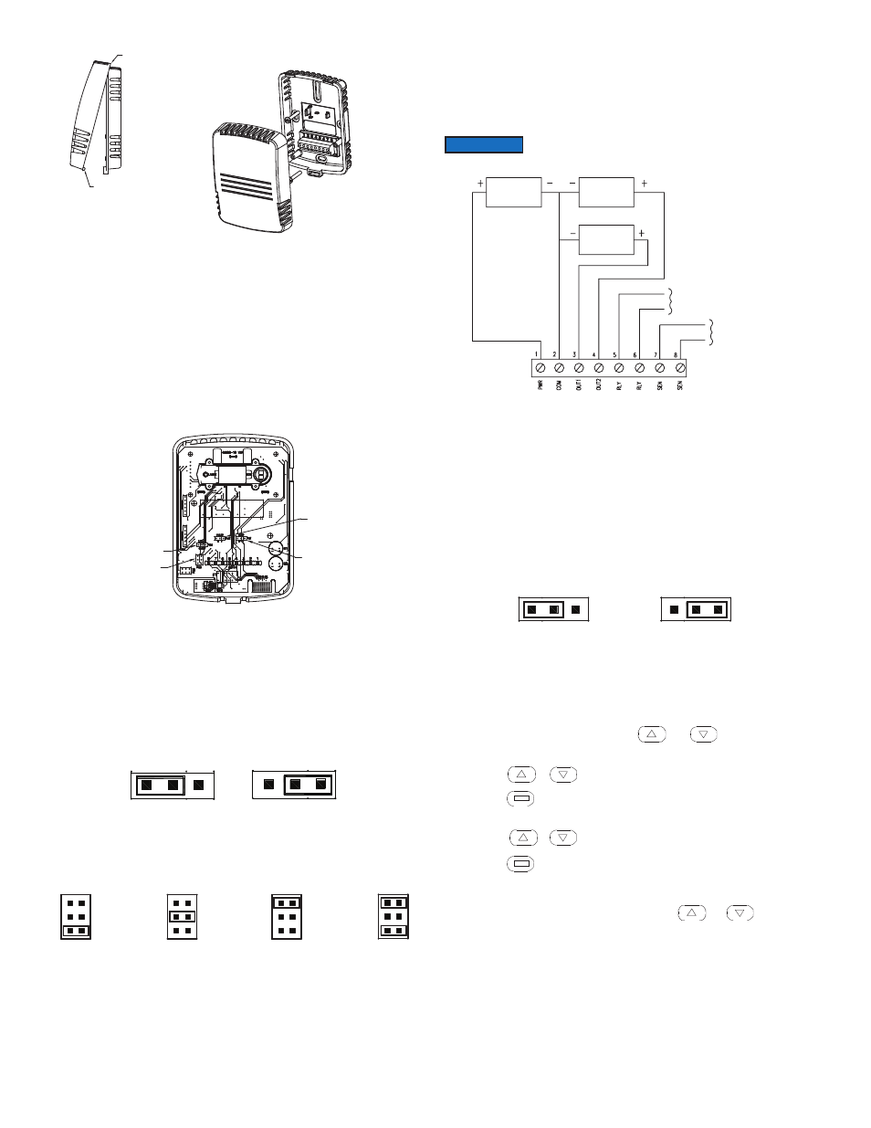
WIRING
Use maximum 18 AWG wire for wiring to terminals. Refer to Figure 5 for wiring
information.
Selection of Current and Voltage Outputs
Prior to wiring, verify that the current/voltage selection jumpers (PJ1, PJ2, and PJ5)
are set to the desired output type. Refer to Figure 2 to locate the selection jumpers.
See Figure 3 for diagram of the current/voltage selection jumper. For voltage output
selection, the output can be 0 to 10 VDC, 0 to 5 VDC, 2 to 10 VDC or 1 to 5 VDC.
See Figure 4 for the type of voltage output selection jumper (PJ5).
Current / Voltage Outputs
On the CDT, the transmitter may be wired for current or voltage output for both carbon
dioxide and temperature. On the CDTR, the transmitter may be wired for current or
voltage output for both carbon dioxide and humidity. The transmitter can be powered
with either 16 to 35 VDC or 19 to 28 VAC. Wire the transmitter according to Figure 5.
Remote Display
For models that are ordered without an integral LCD display, remote display Model
A-449 can be used to display the temperature, humidity, and carbon dioxide. The mini
USB plug of the remote display plugs into the receptor on the side of the housing.
After a short warm up time, the display will begin to show the current temperature and
carbon dioxide measurements unless configured by the user to show humidity and
carbon dioxide, only temperature, only humidity, or only carbon dioxide.
EDITING MENU pARAMETERS
Before any adjustment can be made to the transmitter, the Menu Lockout Jumper
(PJ4) must be set to the ˝On˝ position (See Figure 6).
ACCESSING MENU pARAMETERS
Step 1: To enter the menu structure, press and simultaneously for
5 seconds (display will show RON parameter).
Step 2: Press or to cycle between menu items.
Step 3: Press to edit the value for the displayed menu item (SET will appear
on display).
Step 4: Press or to adjust the value of the menu item.
Step 5: Press to save the changes (SET will disappear).
Step 6: Repeat Steps 2 through 5 for each of the parameters.
Step 7: To exit the menu at any time, press and hold and
simultaneously for 5 seconds or wait 10 seconds without pushing any buttons.
HINGE
BOTTOM TAB
SELF-LATCHING
COVER
MOUNTING
BACK PLATE
MOUNTING
SCREWS
TO REMOVE COVER
APPLY PRESSURE TO
BOTTOM TAB WHERE
INDICATED AND THE
TWO PARTS WILL
BECOME UNHINGED
AT TOP
REVERSE PROCESS
TO APPLY COVER
CURRENT
OUTPUT
VOLTAGE
OUTPUT
C
C
V
V
F
2 to10 V
4 to 20 mA
0 to 10 V
0 to 20 mA
0 to 5 V
0 to 10 mA
1 to 5 V
2 to 10 mA
PASSIVE
TEMPERATURE
SENSOR
RELAY
CONTACT
POWER
SUPPLY
TEMP OR RH
RECEIVER
CO2
RECEIVER
figure 1: Removal Of Cover from Back plate
fIGURE 3: Current/Voltage Output
Selection Jumper (pJ1 And pJ2)
figure 4: Output Range Selection Jumper (pJ5)
figure 5: Active Output Wiring Diagram
figure 2: Diagram Of Circuit Board
1
P1
SE
NS
2
PJ2
PJ1
PJ4
PJ5
ENABLED
DISABLED
OFF
MENU
MENU
PJ4
PJ4
OFF
ON
ON
figure 6: Menu Lockout Jumper
Optional relay can be used as either a dry contact or low voltage
switched circuit up to 2 A at 30 VDC.
NOTICE