Dwyer TFLS User Manual
Page 3
Wiring
Warning: Always install or service this device with the power off
and where required install a disconnect lockout.
Caution: For power line connections use NEC Class 1 wiring rated
60°/75°C. Use 12 to 20 AWG copper only for line and load
connections. Strip the wires 1/4˝.
Note: Installation must be made in accordance with National
Electric Code and local codes and regulations. When fishing wire
through the conduit connection do not allow the wire to touch or
press on components on the boards. Damage to the circuitry may
result.
The TFLS has a 3/4˝ NPT female conduit connection. The conduit
connection must be made such that condensation is not allowed to
enter the housing. If nonmetallic conduit is used, the protective
ground may be connected to the external ground connection
screw.
Strip 1/4˝ of insulation from wires. Connect the power wires to
terminals 4 and 5 if powered by 24 VDC and terminals 1, 2, and 3
if powered by 90 to 265 VAC. Only one type of power supply may
be used at a time, do not connect both AC and DC power
simultaneously. Connect control lines to the relay contact terminals
6, 7, and 8. See Figure 3 for terminals layout.
Figure 3: Terminals
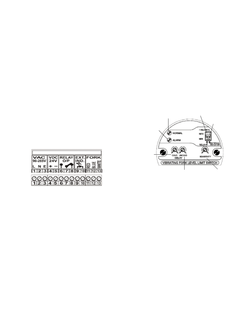
CONTROLS AND INDICATORS (See Figure 4)
Sensitivity Potentiometer — This control sets the sensitivity for
different types of material.
Time Delay Potentiometers — These controls select the delay
times from 2 to 20 seconds from the detection of a level change to
the output. There is one setting for the probe getting covered by
material and one setting for the probe becoming uncovered by
material.
Dip Switch — This two section switch selects the external LED
status and failsafe mode.
Normal LED — Green. This LED is illuminated when the unit is
powered and the fork does not sense any material.
Alarm LED — Red. This LED is illuminated when the relay is
powered by the fork sensing material. It is affected by the delay
setting.
External LED — Red. This external LED is illuminated in
conjunction with the fork being covered or uncovered.
Figure 4:
Switches and LED’s
SETUP AND CALIBRATION
1. Fail Safe Mode Selection: The relay will always be off when the
power fails. In this case the contacts identified as normally open
will be open. The fail safe switch selects whether the normally
open contacts are open or closed when the probe is uncovered.
There are two options for the failsafe condition that are selected by
the RELAY DIP switch (See Figure 4). Selecting MAX will force the
relay contacts to be open when the probe is uncovered and the
NORMAL green LED to be on. Selecting MIN will energize the
relay (closed) when the probe is uncovered and the ALARM red
LED to be on.
2. External LED Selection: The red external LED indicates
material sensing status. There are two options for the LED
condition that are selected by the EXTERNAL INDICATOR DIP
switch (See Figure 4). Selecting MAX will make the LED illuminate
when the probe is uncovered. Selecting MIN will make the LED
illuminate when the probe is covered.
Bulletin L-33
page 3
Failsafe
External LED
Normal Status LED
(Green)
Alarm Status LED
(Red)
Probe Covered
Time Delay
Potentiometer
Probe Uncovered
Time Delay
Potentiometer
Sensitivity