Dwyer TFLS User Manual
Page 2
Bulletin L-33
page 2
OPERATING PRINCIPLE
The TFLS incorporates a piezoelectric crystal that vibrates the fork
at its natural frequency, 85 Hz. When the fork comes in contact
with material the vibration is dampened and the switch changes
state. As the fork becomes free of material the switch changes
back to its normal state.
INSTALLATION
Unpacking
Remove the TFLS from the shipping carton and inspect for
damage. If damage is found, notify the carrier immediately.
Mounting Location
The TFLS is rated for industrial environments with few restrictions,
however certain considerations must be made to ensure for
optimal sensing and extended operational life.
• The process temperature and ambient temperature must be
with- in the specified limits for the instrument.
• It is recommended to use a suitable material to protect and seal
the process threads such as TFE tape.
• Position the tines using a wrench on the hexagonal flats above
the process connection. Do not position by turning the housing.
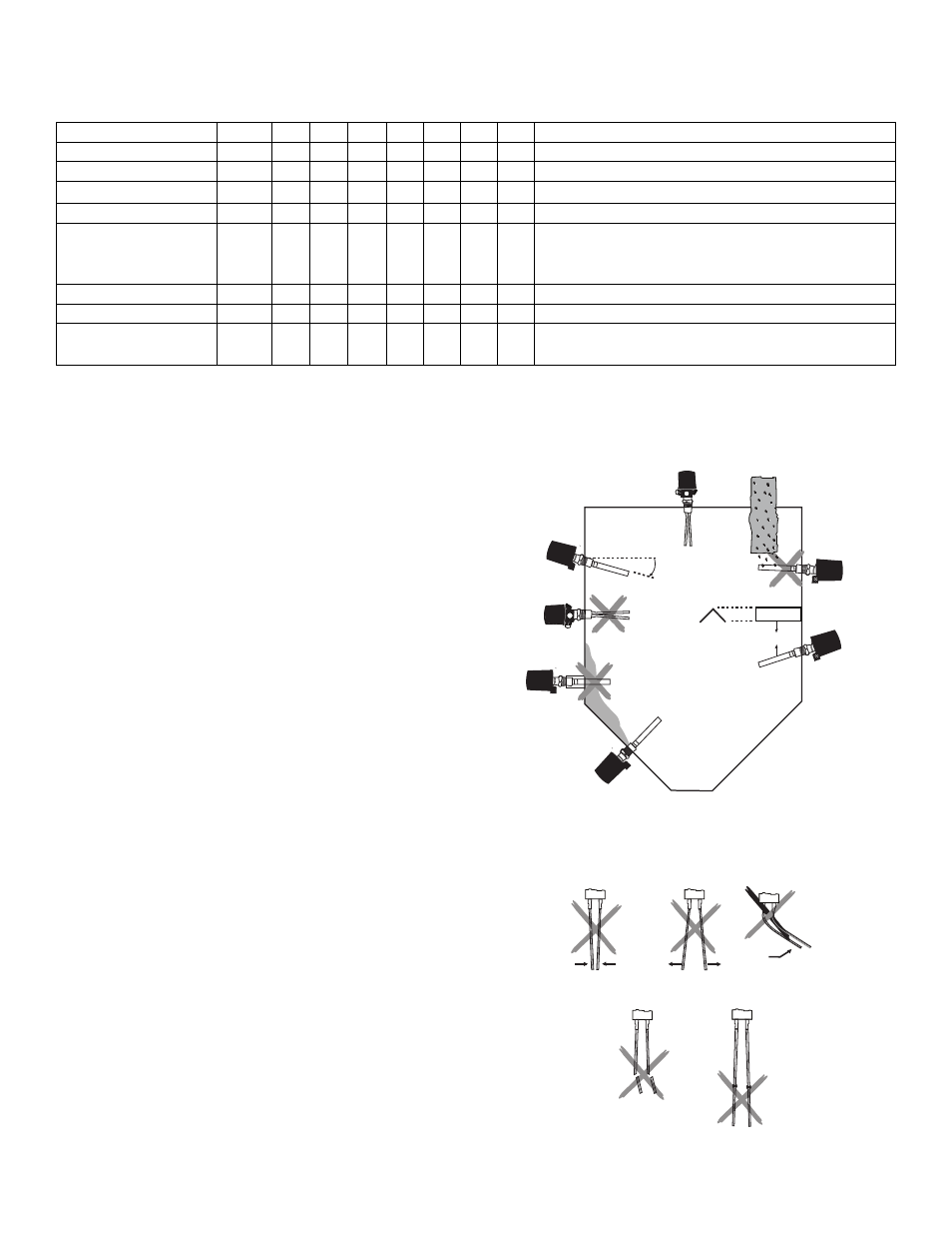
• The probe must be located away from tank inlets or chutes
where material may fall on the probe during filling or emptying
(Figure 1, No. 2). If this is not possible a baffle may be installed
above the probe to protect it from falling material (Figure 1, No. 3).
The baffle must be installed a minimum of 8” (200 cm), see
dimension A in Figure 1, above the probe so that material will not
become packed between the probe and the baffle.
• For mounting horizontally install with conduit entry facing down
so condensate does not enter the enclosure.
• For mounting horizontally position the tines vertically, narrow
edges up, so that material flows freely through them. The TFLS is
designed so that if the conduit opening is pointed down the tines
will be in the proper orientation. No. 6 in Figure 1 shows incorrect
mounting, No. 7 correct mounting.
• For mounting horizontally with materials that may stick to the
tines it is recommended to mount the probe angled down so that
material slides off easily (Figure 1, No. 7).
• The tines should not be bent, shortened, lengthened, or altered
in any way (See Figure 2).
• For top mounting the tines can be mounted in any position
(Figure 1, No. 1).
• When using mounting nozzles, make sure the length is proper so
that the tines extend far enough into the vessel to vibrate free of
material buildup on the vessel wall. Also make sure the nozzle
does not extend further than necessary into the vessel (Figure 1,
No. 5).
Figure 1: Installation Guide
Figure 2: Fork Protection
MODEL CHART
Example
Series
Enclosure
Switch
Power Supply
Probe Type
Process Connection
Probe Length
Options
TFLS
TFLS
W
W
1
1
048
XXX
1
1
EC
SR
EC
ES
1
1
TFLS-W11EC1-048-MT
Tuning Fork Level Switch
Weatherproof
SPDT rated 5A @ 120/240 VAC
24 VDC, 90-265 VAC
Standard Rod
Extension Carbon Steel
Extension 316 SS
1-1/2˝ NPT male
Insertion length in inches (Only for probe type E)
M25 conduit connection
316 SS Enclosure
MT
MT
SS
Do Not Bend
Do Not Shorten
or Extend
A
1
2
3
4
5
6
7