Proximity controls – Dwyer PLS User Manual
Page 4
General
If a control is mounted on the side wall of a bin, the conduit entry should be directed
downwards. Also there should be ample clearance for cover removal. Paddles are
secured to the extensions with a 1/4˝ NPT and 1/8˝ diameter roll pin. Care should be
taken to press pins flush without damaging the bearings of the control.
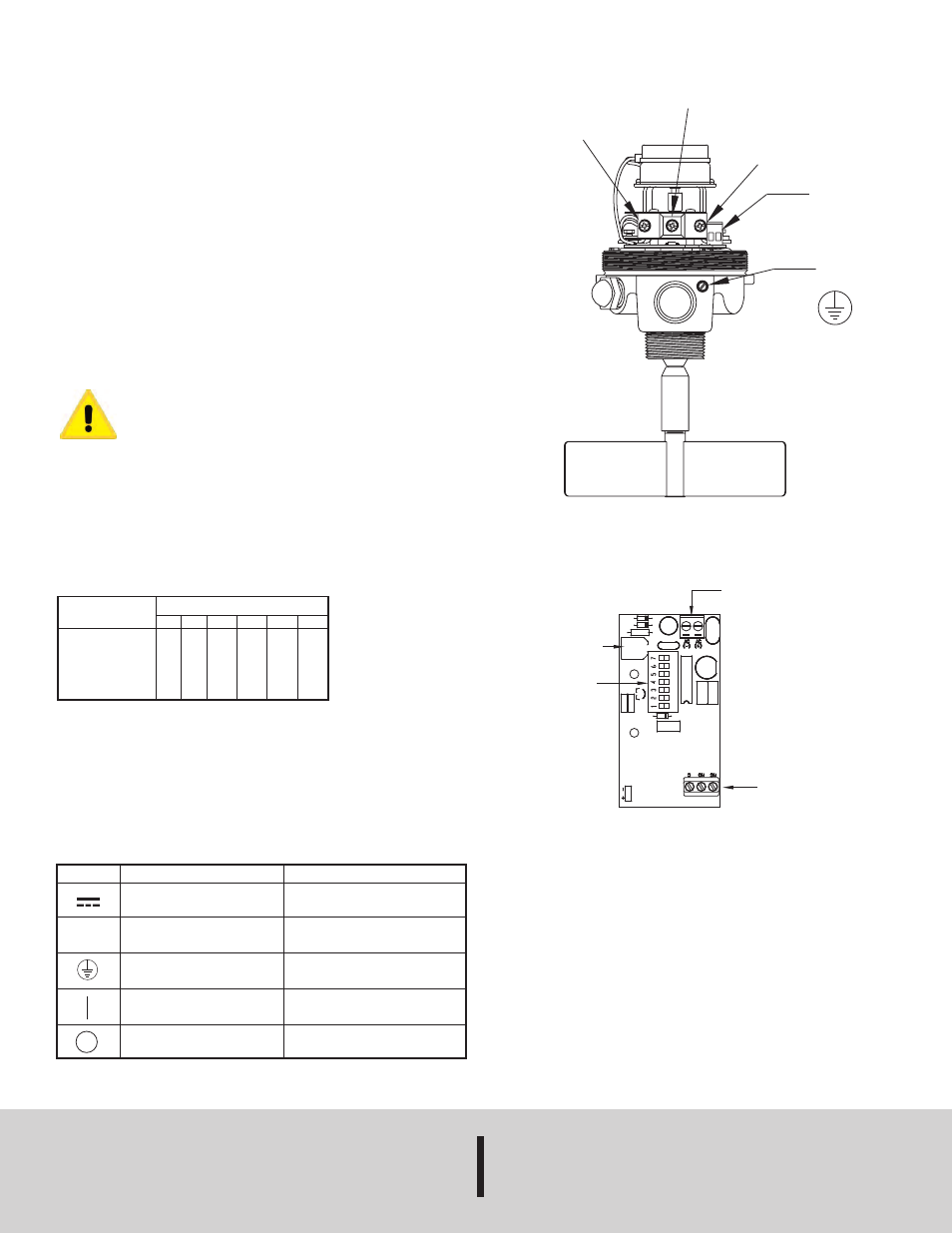
Electrical
Make electrical connections per the wiring diagram for output switch options select-
ed. Wire in accordance with local codes. For hazardous locations, a sealing fitting
must be located within 18˝ of the control.
Wiring
An external switch or circuit breaker should be added to during the installation as a
disconnecting device. The switch or circuit breaker must meet the requirements of
IEC 60947-1 and IEC 60947-3, shall disconnect all current carrying conductors, and
shall not interrupt the protective earth ground. The disconnecting switch or circuit
breaker must be marked or labeled with the symbols “I” for on and “O” for off, per IEC
60417-5007 & IEC 60417-5008 and shall be marked as “Disconnecting Device”. Do
not position the PLS in a space where it is difficult to operate the disconnecting device
that provides power. 300V @ 105°C 18 AWG/0.75 mm
2
wiring with PVC or equivalent
insulation with 94-V0 or FV-0 flammability rating is recommended for the switch out-
puts and power.
As a permanently installed piece of equipment, a power disconnect
switch, circuit breaker, or other approved disconnect device must be
installed in close proximity to the installed board and within easy reach
of the operator. This disconnect device must include a label indicating
its function as a mains disconnect. A 15amp circuit breaker or fuse
device is recommended.
Time Delay
With the DIP position 1 set to “off” the delay is upon energizing of the relay, and with
it set to “on” the delay is upon de-energizing of the relay. Select delay range wanted
from the chart and set the dip switches to the appropriate positions. Then adjust the
one-turn (360˚) potentiometer for the exact time interval required within the selected
delay range. Example: If a 5 minute delay is required, set DIP switches to 0-7 minute
position. Then use potentiometer to adjust to 5 minute period.
MAINTENANCE
Upon final installation of the Series PLS Paddle Level Switch, no routine maintenance
is required. A periodic check of system calibration is recommended. The Series PLS
is not field serviceable and should be returned if repair is needed (field repair should
not be attempted and may void warranty). Be sure to include a brief description of the
problem plus any relevant application notes. Contact customer service to receive a
return goods authorization number before shipping.
©Copyright 2011 Dwyer Instruments, Inc.
Printed in U.S.A. 9/11
FR# 85-442245-00 Rev. 4
PROXIMITY CONTROLS
Phone: 219/879-8000
www.dwyer-inst.com
A DIVISION OF DWYER INSTRUMENTS, INC.
Fax: 219/872-9057
e-mail: [email protected]
P.O. BOX 373 • MICHIGAN CITY, INDIANA 46361, U.S.A.
POTENTIOMETER
DIP
SWITCH
120 OR 230 VAC
POWER INPUT
(DEPENDING ON
MODEL)
RELAY OPTIONS
(ONE SET OR TWO
SETS OF SWITCHES
DEPENDING ON
MODEL)
Time Delay
Range in Minutes
0-1
0-3
0-7
0-15
0-31
STANDARD CONTROL WIRING DIAGRAM
TIME DELAY OPTION WIRING DIAGRAM
2
ON
ON
ON
ON
ON
3
ON
ON
ON
ON
ON
4
OFF
ON
ON
ON
ON
5
OFF
OFF
ON
ON
ON
6
OFF
OFF
OFF
ON
ON
7
OFF
OFF
OFF
OFF
ON
Dip Switch Positions
NC
NO
COM
POWER INPUT
TERMINALS
+ –
GROUNDING
SCREW
Description
Direct current
Alternating current
Protective conductor terminal
On (supply)
Off (supply)
Symbol
Explanation of Symbols:
~
Publication
IEC 50417 - 5031
IEC 50417 - 5032
IEC 50417 - 5019
IEC 50417 - 5007
IEC 50417 - 5008