Dwyer PLS User Manual
Page 2
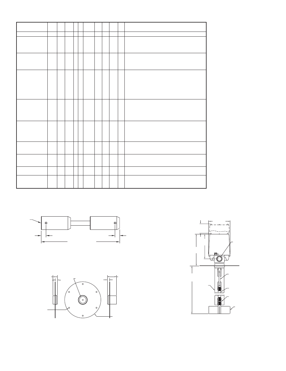
CLEARANCE FOR
COVER REMOVAL
4-1/2
[113.69]
4-11/32
[110.31]
3/4˝ CONDUIT
CONNECTION
FLEXIBLE
COUPLING
(OPTIONAL)
SHAFT
EXTENSION
1/4˝ PIPE
COUPLING
PADDLE
SHAFT
GUARD
OVERALL SHAFT LENGTH
SPECIFIED ORDER
6-3/8
[162.05]
4-31/32
[126.19]
TOP MOUNT
Example
Series
Construction
Switch
Power
Supply
Paddle
Flange
Shaft
Extension
Material
Protective
Shield
Shaft Extension
and Shield Length
Options
PLS-W-S-1-1-SSF-SS-SS-024-FC
Paddle Level Switch
Weatherproof
Explosion-proof
Weatherproof High Temperature
Explosion-proof High Temperature
SPDT
DPDT
DPDT Time Delay – 120 VAC
DPDT Time Delay – 230 VAC
110-120 VAC
230 VAC
24 VAC
48 VAC
12 VDC
24 VDC
230 VAC CE Compliant
No paddle for Motor Control Only Style Low Density
Paddle (PDL-1)
Medium Density Paddle (PDL-2)
Bayonet Paddle (PDL-3)
High Density Paddle (PDL-4)
No Mounting Flange
Carbon Steel with Half Coupling (FLG-CSH)
Carbon Steel with Full Coupling (FLG-CSF)
316 SS with Half Coupling (FLG-SSH)
316 SS with Full Coupling (FLG-SSF)
None
1/4˝ NPS Galvanized Steel
1/4˝ NPS 316 SS
None
1-1/4˝ NPS Galvanized Steel
1-1/4˝ NPS 316 SS
Specify length in inches. Minimum 6, Maximum 48.
May go longer on custom ordered product.
Reversed Light – light indication when paddle free
rotating
Flexible Coupling (CPL-FLX)
PLS
PLS
W
W
E
WH
EH
S
S
D
TD1
TD2
1
1
2
3
4
5
6
7
1
0
1
2
3
4
SSF
0
CSH
CSF
SSH
SSF
SS
0
GS
SS
024
XXX
FC
RL
FC
1
[25.40]
SIX 11/32 [8.74]
HOLES ON
7˝ [177.80] B.C.
HALF COUPLING
FLG-CSH
FLG-SSH
FULL COUPLING
FLG-CSF
FLG-SSF
8˝ O.D.
[203.20]
15/32
[11.94]
1-1/4 NPT
15/32
[11.94]
MOUNTING FLANGE
FLEX COUPLING, MODEL CPL-FLX
1/4 NPT
9/32
[7.14]
1/4 [6.35]
4-13/32 [111.92]
MODEL CHART
SS
0
GS
SS