Dwyer 628 User Manual
Page 3
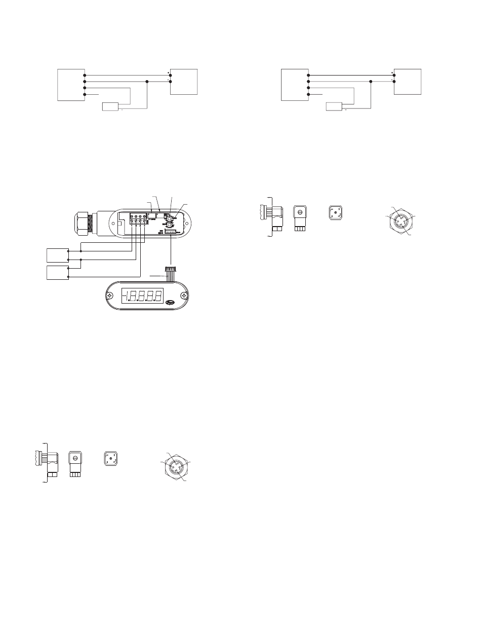
VOLTAGE (0-5, 1-5, 0-10, 1-6 or 2-10 VDC) OuTPuT OPERATION
(Other outputs contact the factory) See Fig. F for connection of the power supply,
transmitter and receiver.
Conduit Housing (-CH) Electrical connections to the pressure transmitters are
made to the terminal block located inside the housing. Remove the screws and lift
off the cover. Wire as shown in Fig. F or Fig. G. Use Fig. F for voltage output
connection. Use Fig. G for voltage output with optional LED display connection. If
ordering optional pre-wired cable, black wire is negative (-), red wire is positive (+)
and white wire is +Vout.
Heirschman DIN Connector with Voltage Output When using cable version of
-GH General Purpose Housing, black wire is negative (-), red wire is positive (+)
and white wire is output. When using optional Heirschman DIN Plug, remove top-
center screw and lift off the terminal block assembly. Wire to terminals shown
below in Fig. H. For optional 4-pin M-12 connector, wire to pins as shown in Fig. I.
If utilizing optional A-164 cable for M-12 connection, brown wire corresponds to pin
#1, white #2, blue #3, and black #4.
SPAN
ZERO
PRESS AND
HOLD TO ZERO
THE DISPLAY
PRESS TO
DISPLAY THE
GAGE’S
PRESSURE
RANGE
LED DISPLAY
CONNECTOR
YELLOW
OPTIONAL LED DISPLAY
TERM 1 (+)
TERM 2 (-)
TERM 3 (-)
TERM 4 (+)
BE SURE TO TURN OFF POWER WHEN
CONNECTING OR REMOVING THE
DISPLAY’S CONNECTOR. FAILURE TO DO
SO CAN RESULT IN THE GAGE DAMAGE.
TRANSMITTER CONNECTION:
- TURN OFF POWER
- CONNECT POWER SUPPLY
(+) TO TERMINAL 1
- CONNECT POWER SUPPLY
(-) TO TERMINAL 2 AND TO
THE RECEIVER (-)
- CONNECT THE RECEIVER
(+) TO TERMINAL 3
- CONNECT LED POWER SUPPLY
(+) TO TERMINAL 4
- INSTALL THE DISPLAY’S
CONNECTOR
- TURN ON POWER
LED DISPLAY POSITIVE SUPPLY
+
-
-
+
+ V OUT
RECEIVER
POWER
SUPPLY
Fig. G: Voltage output with optional LED display connection
PRESSURE
TRANSMITTER
1 RED
2 BLACK (COMMON)
3 WHITE (+V OUT)
4 (NC)
RECEIVER
+V in
POWER
SUPPLY
V
Fig. F: Voltage output connection
Voltage Output
A
A
SECTION A-A
TERMINAL 1: (+)
TERMINAL 2: (-)
TERMINAL 3: [OUTPUT]
Fig. H
TERMINAL 1: (+)
TERMINAL 4: (-)
TERMINAL 3: (GROUND)
TERMINAL 2: (Vout)
Fig. I
RATIOMETRIC (0.5-4.5 VDC) OuTPuT OPERATION
(Other outputs contact the factory) See Fig. J for connection of the power supply,
transmitter and receiver.
General Purpose Housing with Ratiometric Output When using cable version
of -GH General Purpose Housing, black wire is negative (-), red wire is positive (+)
and white wire is output. When using optional Heirschman DIN Plug, remove top-
center screw and lift off the terminal block assembly. Wire to terminals shown
below in Fig. K. For optional 4-pin M-12 connector, wire to pins as shown in Fig. L.
If utilizing optional A-164 cable for M-12 connection, brown wire corresponds to pin
#1, white #2, blue #3, and black #4.
MAINTENANCE
After final installation of the pressure transmitter and its companion receiver, no
routine maintenance is required. A periodic check of system calibration is
suggested. The Series 626 and 628 transmitters are not field repairable and should
be returned if repair is needed (field repair should not be attempted and may void
warranty). Be sure to include a brief description of the problem plus any relevant
application notes. Contact customer service to receive a return goods authorization
number before shipping.
PRESSURE
TRANSMITTER
1 RED
2 BLACK (COMMON)
3 WHITE (+V OUT)
4 (NC)
RECEIVER
+V in
POWER
SUPPLY
5 VDC
±10%
Fig. J: Voltage output connection
Voltage Output
A
A
SECTION A-A
TERMINAL 1: (+)
TERMINAL 2: (-)
TERMINAL 3: [OUTPUT]
Fig. K
TERMINAL 1: (+)
TERMINAL 4: (-)
TERMINAL 3: (GROUND)
TERMINAL 2: (Vout)
Fig. L