Dwyer 628 User Manual
Page 2
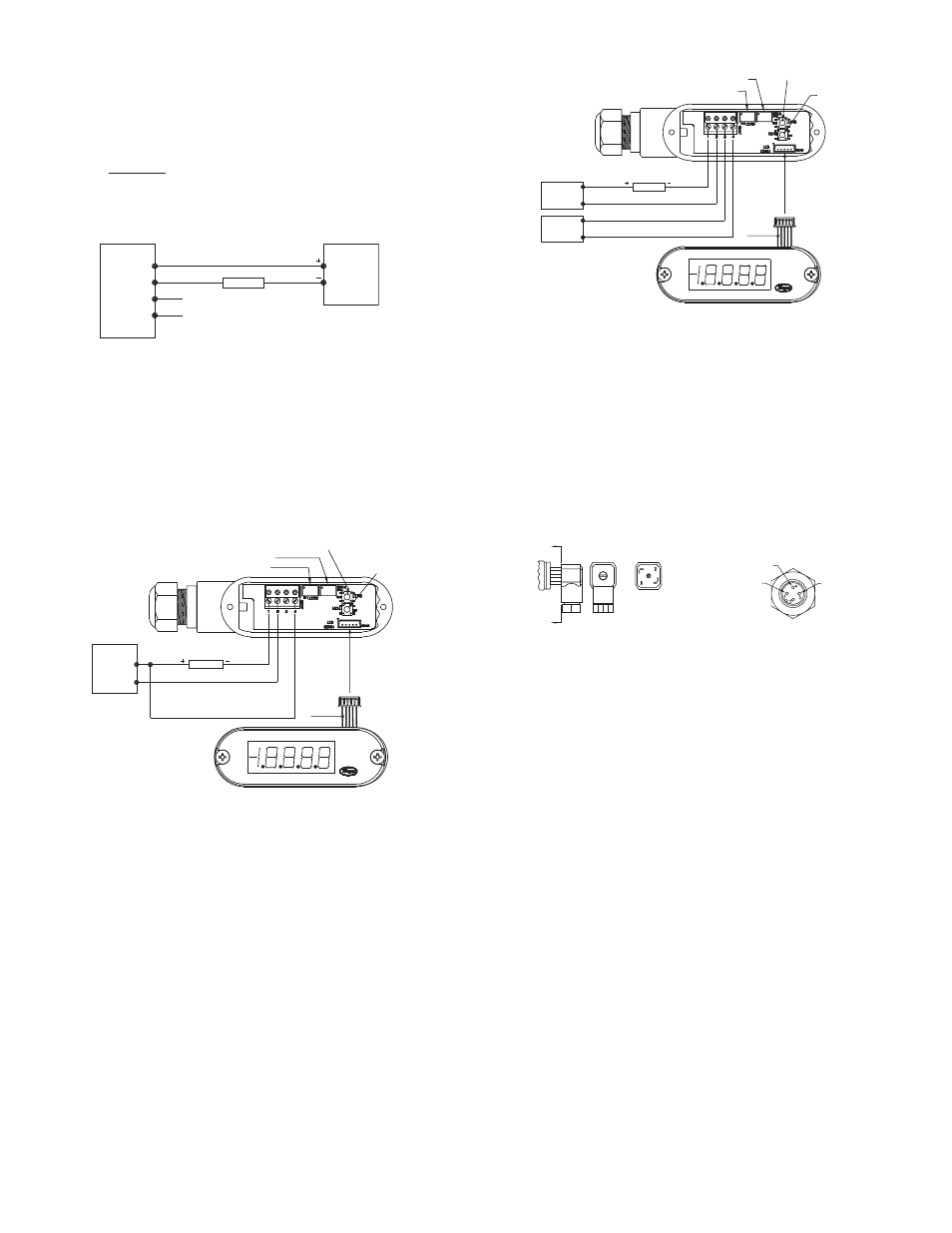
CuRRENT (4-20 mA) OuTPuT OPERATION
An external power supply delivering 10-30 VDC with minimum current capability of
40 mA DC (per transmitter) is required to power the control loop. See Fig. A for
connection of the power supply, transmitter and receiver. The range of appropriate
receiver load resistance (R
L
) for the DC power supply voltage available is
expressed by the formula:
Shielded cable is recommended for control loop wiring.
Conduit Housing with 4-20 mA Output (-CH) Electrical connections to the
pressure transmitters are made to the terminal block located inside the housing.
Remove the screws and lift off the cover. Wire as shown in Fig. A, B or C. Use Fig.
A for current output connection. Use Fig. B for current output with optional LED
display. Use Fig. C for current output with optional LED display using two power
supplies.
If ordering optional pre-wired cable, black wire is negative (-) and red wire is
positive (+).
R
L
Max = Vps – 10
20 mA DC
1 RED
2 BLACK
3 (NC)
4 (NC)
+ RECIEVER -
mA
PRESSURE
TRANSMITTER
POWER
SUPPLY
10-30 VDC
Fig. A: Current output connection
Current Output
Fig. B: Current output with optional LED display connection
SPAN
ZERO
PRESS AND HOLD TO
ZERO THE DISPLAY
PRESS TO DISPLAY
THE GAGE’S
PRESSURE RANGE
YELLOW
LED DISPLAY CONNECTOR
TERM 1 (+)
TERM 2 (-)
TERM 4 (+)
OPTIONAL LED DISPLAY
RECEIVER
mA
LED DISPLAY
POSITIVE SUPPLY
10-30 VDC
(140 ma)
POWER
SUPPLY
+
-
TRANSMITTER CONNECTION:
- TURN OFF POWER
- CONNECT THE POWER SUPPLY
AND RECEIVER TO TERM 1 AND
TERM 2 OF THE GAGE AS SHOWN
- CONNECT POWER SUPPLY (+) TO
TERMINAL 4 (REQUIRED FOR THE
OPTIONAL DISPLAY ONLY)
- INSTALL THE DISPLAY’S CONNECTOR
- TURN ON POWER
BE SURE TO TURN OFF POWER WHEN
CONNECTING OR REMOVING THE
DISPLAY’S CONNECTOR. FAILURE TO DO
SO CAN RESULT IN THE GAGE DAMAGE.
SPAN
ZERO
PRESS AND
HOLD TO ZERO
THE DISPLAY
PRESS TO
DISPLAY
THE GAGE’S
PRESSURE
RANGE
LED DISPLAY
CONNECTOR
YELLOW
OPTIONAL LED DISPLAY
10-30 VDC
(40 ma)
10-30 VDC
(100 ma)
+
-
+
-
RECEIVER
mA
LED DISPLAY NEGATIVE SUPPLY
LED DISPLAY POSITIVE SUPPLY
TERM 1 (+)
TERM 2 (-)
TERM 3 (-)
TERM 4 (+)
BE SURE TO TURN OFF POWER WHEN
CONNECTING OR REMOVING THE
DISPLAY’S CONNECTOR. FAILURE TO DO
SO CAN RESULT IN THE GAGE DAMAGE.
TRANSMITTER CONNECTION:
- TURN OFF POWER
- CONNECT THE POWER SUPPLY AND
RECEIVER TO TERM 1 AND TERM 2
OF THE GAGE AS SHOWN
- CONNECT LED POWER SUPPLY (-)
TO TERMINAL 3
- CONNECT LED POWER SUPPLY (+)
TO TERMINAL 4
- INSTALL THE DISPLAY’S CONNECTOR
- TURN ON POWER
POWER
SUPPLY
LED SUPPLY
POWER SUPPLY
Fig. C: Current output with optional LED display using two power supplies
Fig. D
A
A
SECTION A-A
TERMINAL 1: (+)
TERMINAL 2: (-)
TERMINAL 3: (GROUND)
TERMINAL 4: (-)
TERMINAL 1: (+)
T
Fig. E
Heirschman DIN Connector with 4-20 mA When using cable version of -GH
General Purpose Housing, black wire is negative (-) and red wire is positive (+).
When using optional Heirschman DIN Plug, remove top-center screw and lift off the
terminal block assembly. Wire to terminals shown below in Fig. D. For optional 4-
pin M-12 connector, wire to pins as shown in Fig. E.