Dwyer instruments, inc – Dwyer 616KD User Manual
Page 2
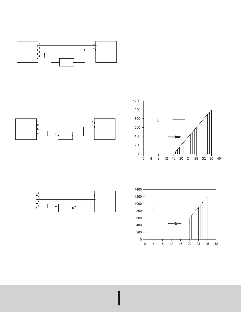
Voltage Units (0 to 5 or 0 to 10 V)
An external power supply delivering 16 to 35 VDC or 20 to 28 VAC with
minimum current capability of 16 mA DC (per transmitter) must be used to
power the control loop. Connect terminals 3 & 4 to select the 0 to 5 V output
mode. Leave terminal 4 disconnected to select the 0 to 10 V output mode.
See Figure A for connection of the power supply, transmitter and receiver.
2-Wire Operation (4 to 20 mA units)
An external power supply delivering 16 to 35 VDC with minimum current
capability of 21 mA DC (per transmitter) must be used to power the control
loop. See Figure B for connection of the power supply, transmitter and
receiver. The range of appropriate receiver load resistance (RL) for the DC
power supply voltage available is expressed by the formula and graph in
Figure D.
3-Wire Operation (4 to 20 mA Units)
An external power supply with minimum current capability of 21 mA DC
(per transmitter) delivering 16 to 35 VDC or 20 to 28 VAC is required. See
Figure C for connection of power supply, transmitter and receiver. The
range of appropriate receiver load resistance (RL) of DC and AC power
supplies is expressed by the formula and graph in Figures D & E.
Zero Adjustment
Allow transmitter to warm up for 30 minutes. Transmitter should be zeroed
at the temperature it is to be operated at.
A single push button is provided to zero the transmitter. Span is factory
calibrated to the range specified on the label. There is no user span
adjustment necessary.
MAINTENANCE/REPAIR
Upon final installation of the Series 616KD no routine maintenance is
required. The Series 616KD is not field serviceable and should be returned
if repair is needed. Field repair should not be attempted and may void
warranty.
WARRANTY/RETURN
Refer to “Terms and Conditions of Sales” in our catalog and on our website.
Contact customer service to receive a Return Goods Authorization number
before shipping the product back for repair. Be sure to include a brief
description of the problem plus any additional application notes.
DWYER INSTRUMENTS, INC.
Phone: 219/879-8000
www.dwyer-inst.com
P.O. BOX 373 • MICHIGAN CITY, INDIANA 46360, U.S.A.
Fax: 219/872-9057
e-mail: [email protected]
MAXIMUM LOOP RESISTANCE (DC POWER)
MAXIMUM VALUE (1000 Ω)
T
O
TA
L
LO
O
P
R
E
S
IS
TA
N
C
E
(
Ω
)
POWER SUPPLY VOLTAGE (VDC)
OPERATING
REGION
R Max. =
Vps - 16 V
20 mA
MAXIMUM LOOP RESISTANCE (AC POWER)
MAXIMUM VALUE (1200 Ω)
R Max. = 75 Ω/V x Vps - 900 Ω
T
O
TA
L
LO
O
P
R
E
S
IS
TA
N
C
E
(
Ω
)
POWER SUPPLY VOLTAGE (VAC)
OPERATING
REGION
©Copyright 2013 Dwyer Instruments, Inc.
Printed in U.S.A. 8/13
FR# 01-443641-50 Rev. 2
PRESSURE
TRANSMITTER
RECEIVER
POWER SUPPLY
16 TO 36 VDC
OR
20 TO 28 VAC
PRESSURE
TRANSMITTER
RECEIVER
POWER SUPPLY
16 TO 36 VDC
2 - WIRE CONNECTIONS (4 TO 20 mA)
PRESSURE
TRANSMITTER
RECEIVER
POWER SUPPLY
16 TO 36 VDC
OR
20 TO 28 VAC
3 - WIRE CONNECTIONS (4 TO 20 mA)
Figure A
Figure B
Figure C
Figure D
Figure E