Dwyer instruments, inc – Dwyer 668 User Manual
Page 2
©Copyright 2014 Dwyer Instruments, Inc. Printed in U.S.A. 5/14 FR# R8-443095-00 Rev. 2
DWYER INSTRUMENTS, INC.
Phone: 219/879-8000
www.dwyer-inst.com
P.O. Box 373 • Michigan City, IN 46360, U.S.A.
Fax: 219/872-9057
e-mail: [email protected]
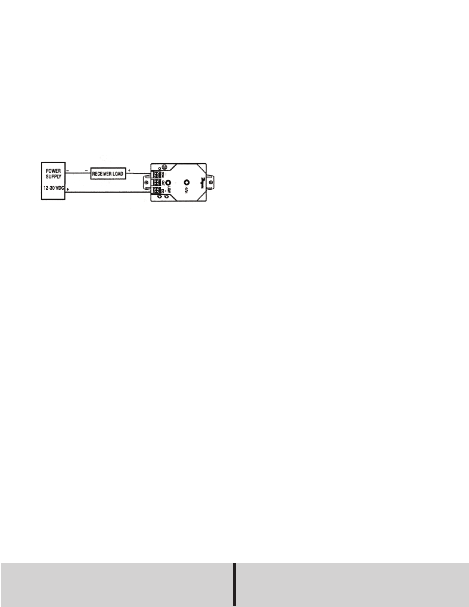
ELECTRICAL CONNECTIONS
The Series 668 Differential Pressure Transmitter is a loop-powered 4 to
20 mA current output unit. The current flows into +EXC. terminal and
returns back to the power supply through the -EXC. terminal. the power
supply must be a DC voltage source with a voltage range between 12
and 30 VDC measured between terminal +EXC. and -EXC.
The unit is calibrated at the factory using a 250 ohm load at 28 VDC.
Notes:
Minimum Supply Voltage (VDC) = 12 + 0.02 x (resistance of receiver
plus line).
Maximum Supply Voltage (VDC) = 30 + 0.004 x (resistance of receiver
plus line).
CALIBRATION
The 668 series is factory calibrated and should require no field adjust-
ment. However, both zero and span adjustments are provided.
Whenever possible, any zero and/or span offsets should be corrected by
software adjustment in the user’s control system. Use the zero and span
adjustments on the 668 Series only if absolutely necessary. The 668
series is calibrated in the vertical position at the factory. For use in other
orientations, position the unit and follow the zero adjustment procedure
listed below. Pressure ranges are fixed and cannot be changed in the
field.
Zero Adjustment
While monitoring the current output with both pressure ports open to
atmosphere, the zero may be adjusted. For unidirectional pressure
ranges, turn the zero adjustment screw until a reading of 4 mA (±0.15
mA) is achieved.
Span Adjustment (Complete the zero adjustment before setting
span)
Span on full scale output adjustments should only be performed by
using an accurate pressure standard (electronic manometer, digital
pressure gage, etc.) with at least comparable accuracy to the 668 series
(<±1% full scale). With full scale pressure applied to the high pressure
port (reference port open to atmosphere) adjust span to achieve 20 mA
output.
Example 1: Unidirectional pressure range of 0 to 1˝ w.c. Apply 1.00˝ w.c.,
adjust span to 20 mA.
Notes: The input is reverse-voltage protected. The output is internally
protected against damage is shorted to ground. Recheck all connections
before applying power.
MAINTENANCE
After final installation of the Series 668 Differential Pressure Transmitter,
no routine maintenance is required. A periodic check of system calibra-
tion is recommended. These devices are not field repairable and should
be returned if recalibration or other service is required. Contact cus-
tomer service to obtain an RGA number. Please include a clear descrip-
tion of the problem plus any application information available.