Dwyer 668 User Manual
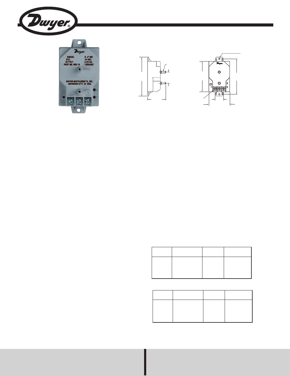
Series 668 differential pressure transmitter, Dwyer instruments, inc
DWYER INSTRUMENTS, INC.
Phone: 219/879-8000
www.dwyer-inst.com
P.O. Box 373 • Michigan City, IN 46360, U.S.A.
Fax: 219/872-9057
e-mail: [email protected]
Our low cost Series 668 Differential Pressure Transmitter is capable of
measuring low pressures with a ±1% accuracy ideally suited for proper
building pressurization and air flow control. Transmitters can withstand
up to 10 psig overpressure with no damage to the unit. Variable capac-
itance sensor design provides excellent sensitivity and long-term stabil-
ity. Compact, lightweight design makes installation simple and easy.
Units also feature reverse-polarity protection.
INSTALLATION
Mounting
The 668 Series is designed for mounting in either a switch box or by
using the two (2) holes that are provided on the housing. Optimum per-
formance is obtained by isolating the instrument from vibration and pro-
viding relatively clean, dry ambient air to the pressure ports. In most
cases, preferred installation is with the baseplate mounted vertically and
located on a relatively flat surface in a junction box or attached to a near-
by beam.
CAUTION: The axis most sensitive to vibration is the one perpendicular
to the mounting base. Avoid mounting with maximum vibration along the
axis.
Pressure Fitting
Two (2) 3/16˝ O.D. pressure fittings are supplied for pressure connec-
tion with 1/4˝ push-on tubing. Both the positive (high) pressure port and
the reference (low) pressure port are located on the top face of the unit,
labeled High and Low respectively. For best results (shortest response
times), 3/16˝ I.D. tubing is suggested for tubing lengths up to 100 feet
long, 1/4˝ I.D. for tubing lengths up to 300 feet, and 3/8˝ I.D. for tubing
lengths up to 900 feet.
Series 668 Differential Pressure Transmitter
Specifications - Installation and Operating Instructions
Bulletin A-30-668
SPECIFICATIONS
Service: Air and non-conductive gases.
Accuracy: ±1% of full scale (RSS)
(includes non-linearity, hysteresis, and non-repeatability).
Temperature Limits:
Operating: 0 to 150°F (-18 to 65°C);
Storage: -40 to 185°F (-40 to 85°C).
Pressure Limits: 10 psig (0.7 kg/cm
2
).
Compensated Temperature Range: 0 to 150°F (-18 to 65°C).
Thermal Effects: 0.033% FS/°F (0.018% FS/°C).
Supply Voltage: 12-30 VDC.
Output: 4 to 20 mA, 2-wire.
Zero and Span Adjust: ±1 mA, non-interactive.
Response Time: <60 msec.
Loop Resistance: 0-800 ohms.
Electrical Connection: Terminal strip.
Pressure Connection: 3/16 9 O.D. fitting for 1/49 I.D. tubing.
Housing: Fire retardant glass filled polyester.
Weight: 3 oz (85 g).
Agency Approvals: CE.
Ø5/32 [3.97]
MOUNTING HOLE
TYP 2 PLACES
3-5/32
[80.16]
3/8
[9.53]
1-7/8
[47.63]
6-32 SCREW
W/TERMINAL WASHER
2-3/4
[69.85]
1
[25.40]
3/16 [4.76]
FITTING
3-1/2
[88.90]
1-41/64
[41.67]
LOW
HIGH
_
COM
+
EXC
OUT
*Also available with optional conduit cover. To order add “C” to part
number, i.e. 668C-1. Consult factory for additional information.
Models & Ranges
Model
Number*
668-1
668-2
668-3
668-4
Range
0 to 0.25 in w.c.
0 to 0.5 in w.c.
0 to 1 in w.c.
0 to 2.5 in w.c
Model
Number*
668-5
668-6
668-7
668-8
668-9
Range
0 to 5.0 in w.c.
0 to 10 in w.c.
0 to 25 in w.c
0 to 50 in w.c.
0 to 100 in w.c.
Bi-Directional Models
Model
Number*
668-10
668-11
668-12
668-13
Range
0 to ±0.1 in w.c.
0 to ±0.25 in w.c.
0 to ±0.5 in w.c.
0 to ±1 in w.c
Model
Number*
668-14
668-15
668-16
668-17
668-18
Range
0 to ±2.5 in w.c.
0 to ±5 in w.c.
0 to ±10 in w.c
0 to ±25 in w.c.
0 to ±50 in w.c.