Dwyer 3000SGT User Manual
Page 3
5. Dual Set Point Automatic and Manual Reset Combinations: Circuit style HH
may be used with either set-point wired and operating with automatic reset as
described in paragraph 3 above and other set-point wired and operating with
manual reset as described in paragraph 4.
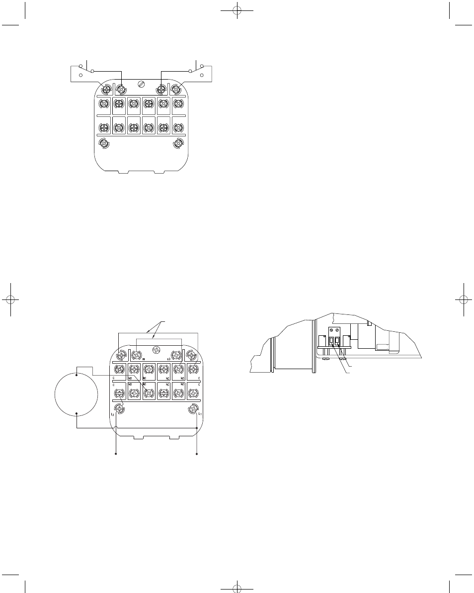
6. High Low Limit Control – Dual Set-Point: Circuit Style HH may be used to
control fans, dampers, pumps, etc., between the set-points of a PHOTOHELIC
®
SGT. To accomplish this, use one set-point relay to reset the other as shown in
the wiring diagram Figure G. In this typical application, the load (for instance a
fan) would be connected to the N.C. contacts of the right set-point relay,
Section A (Figure D). On pressure rise to the right set-point, its relay would pull
in and hold even though pressure might then fall below that set-point. If the
pressure continued to fall to the left set-point, its relay would automatically be
DE-ENERGIZED, returned to its normal position and in so doing, open the
holding coil circuit from Section B (Figure D). The right set-point relay would
thus be reset and the cycle could repeat.
7.
Dual Set-Point Special Purpose Circuits: Circuit Style LL may be used
where manual reset following maintained contact on pressure decrease to
either set-point is desired. Circuit Styles HL and LH are combination units. For
special combinations of features, special units, and detailed instructions
regarding their use, consult the factory.
8.
Single Set-Point PHOTOHELIC
®
SGT: The single set-point PHOTOHELIC
®
SGT is furnished with the right set-point only. Terminals in Sections A and B
(Figure D) are connected to this relay. Circuit Style SRH is wired for automatic
reset as in paragraph 3 above. Manual reset is accomplished by adding a
normally closed reset switch or push button to the circuit as described in
paragraph 4 above.
9.
Single Set-Point Special: Manual reset after actuation on falling pressure
can be obtained by using Circuit Style SRL. Consult the factory for special
units and detailed instructions regarding their use.
10. Placing in Service: In normal operation each relay is de-energized when the
pressure applied to the instrument is below its set-point. Special low-latching
units will ordinarily have to be reset before placing on the line in normal
operation.
11. Failure Mode: The PHOTOHELIC
®
SGT circuit design provides certain
protection in the event of a loss of pressure or electrical power. In either case,
both relays will de-energize, returning to their normal “zero pressure” state.
The exceptions to this are models with center zero ranges. Because the relays
on all standard models are always energized when the indicating (black)
pointer is to the right of their respective set points, the relay action on loss of
pressure will depend on set-point position, since either of them could be
located to the left of zero. As an example; if the left pointer were set at -2 in.
w.c. and negative pressure was -3 in w.c., a loss of that pressure would allow
the black pointer to return to the center and thus cause the low set-point relay
to energize.
If the LED should burn out, only the left-low relay will de-energize. The right-
high relay will react as if pressure were above its set-point and will remain
energized even though pressure might be below that setting. In this situation,
only termination of electrical power will allow the right-high relay to de-
energize.
TRANSMITTER WIRING CONNECTIONS
Electrical connections for the two-wire, 4-20 mA transmitter circuit are made to the
small terminal block mounted behind the larger switch/gage terminal board. Wiring
should enter this area through the 5/8˝ dia. hole at bottom of electronics chassis.
See Figure H.
The transmitter function of the PHOTOHELIC
®
SGT operates independent of the
low/high switch set-points and requires a separate external power supply delivering
10.0 to 35 VDC with minimum current capability of 40mA to power its control loop.
Refer to Figure J for connection of the power supply, transmitter and receiver. The
range of appropriate receiver load resistance (RL) values for various power supply
voltages is defined by the formula and graph in Figure K. Shielded two wire cable
is recommended for control loop wiring and the negative side of the loop can be
grounded if proffered. The receiver can be connected in either the positive or
negative side of the loop. If the polarity of the transmitter or receiver is inadvertently
reversed, the loop will not function properly but no damage will be done to the
transmitter.
The maximum wire length between the transmitter and receiver is a function of wire
size and receiver resistance. Connecting wires should not contribute more than
10% of the receiver resistance to total current loop resistance. Where long runs
(over 1,000 feet) are required, select receivers with higher resistances to minimize
size and thus cost of wiring. For runs up to 100 feet, wire as small as 24 AWG can
be used.
RESET
NC
NO
RESET
NC
NO
HI
LO
C
NO
NC
NC
NO
C
C
NO
NC
NC
NO
C
L 2
L 1
1/3 HP*
120 V
LOAD
RESET JUMPERS
Figure F
Figure G
CAUTION: Do not apply electrical current to terminals in Sections B and C.
Manual Reset with Circuit HH
*Note: For larger motors, use the Photohelic
®
in a maintained contact, 120 Volt
Control or Push Button Circuit of the motor starter.
3
POSITIVE
NEGATIVE
Figure H
B-36A:bulletin B-36A 12/13/10 10:18 AM Page 3