Instructions, Installation, Operation – Crystal WT Series Panel Mount Digital Pressure Gauge User Manual
Page 4
Instructions
4
XP2i External Power Supply Operation Manual
Instructions
—
InstallatIon
Remove the (red) protective cover from DB9 connector on the back of the XP2i. (Save the cover—if you don’t need to use the RS-232 interface, you can use
the cover to protect the DB9 connector on the computer side of the adapter). Connect the side of the DB9 pass-through connector with the captive screws
to the XP2i (Figure 1). If the XP2i is to be permanently installed, screw the captive screws into the DB9 connector.
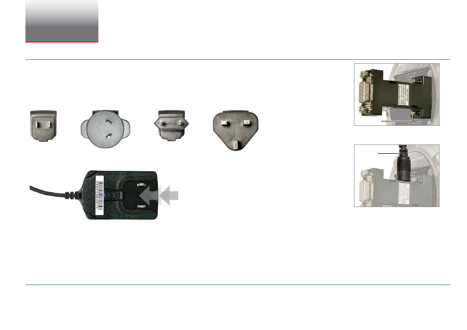
The wall mounted power supply is provided with four types of AC input adapters. Choose the one appropriate for your location…
USA
Australia
Europe
UK
then slide the adapter into the body of the power supply. Make sure it locks securely into place.
Plug the DC power connector (2.1mm x 5.5mm Coaxial Plug) into the matching receptacle on the side of the pass through housing (Figure 2).
Connect the power supply to the AC line.
!
WARNING: do not use the ac adapter kit in a hazardous atmosphere.
!
CAUTION: do not exceed the maximum supply voltage of 264 Vac. always use alkaline batteries.
—
operatIon
The XP2i can be operated from the adapter without batteries installed, although we recommend that batteries remain in the XP2i. The batteries will act as an
automatic backup supply in case of power failure.
To protect the XP2i from power supply failures, or connection of non-approved DC power supplies, the pass-through connector includes a non-serviceable fuse.
Captive Screw
DC Power
Connector
Figure 1. DB9 captive screws
Figure 2. DC power connector to recepticle on
DB9 connector