Caution, 2 footvalve/strainer, 3 outlet tubing – Blue-White C-1500N CHEM-FEED Diaphragm Pump User Manual
Page 6
4.3
How To Install the Tubing and Fittings
4.3.1
Inlet Tubing
- Locate the inlet fitting of the pump head, see fig 4.6. Remove the
tube nut. Push the clear PVC suction tubing onto the compression barb of the
fitting. Use the tube nut to secure the tube. Hand tighten only.
4.3.2
Footvalve/Strainer
-Trim the inlet end of the suction tubing so that the strainer
will rest in a vertical position, approximately one inch from the bottom of the
solution tank. This will prevent sediment from clogging the strainer. Loss of
prime may occur if the footvalve is permitted to lay on the bottom of the solution
tank in a horizontal position. Slip the ceramic weight over the end of the suction
tube. Press the footvalve/strainer into the end of the tube. Secure the ceramic
weight to the strainer. Drop the strainer into the solution tank.
4.3.3
Outlet Tubing
- Locate the outlet fitting of the pump head, see fig 4.6. Remove
the tube nut. Push the opaque outlet (discharge) tubing onto the compression barb
of the fitting. Use the tube nut to secure the tube. Hand tighten only.
Trim the other end of the outlet tube leaving only enough slack to connect it to the
Injection/Check valve Fitting (see below). Increasing the length of the outlet tube
increases the back pressure at the pump head, particularly when pumping viscous
fluids.
Keep the inlet and outlet tubes as short as possible.
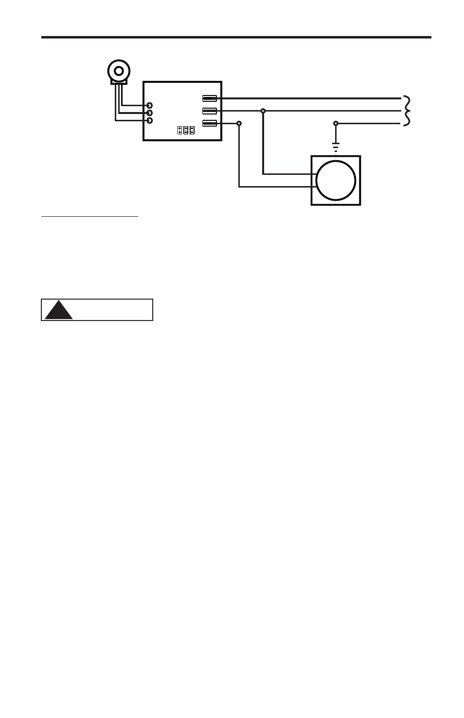
FIG. 4.5 WIRING DIAGRAM - FIXED TIMERS
(factory Setting)
Cycle Adjustment
Potentiometer
T3
T2
T1
AC
Input
Power
Hot
Common
Ground (green)
Timer
Board
Hot
Neutral
AC/LOAD
AC
LOAD
JB2 JB3
JB1
AC
Motor
JB1, JB2, JB3 = Voltage Selector Jumpers
Jumpers Configuration
Install JB2 & JB3, (JB1 left open) = 24 V AC input
Install JB1 & JB3, (JB2 left open) = 115 V AC input
Remove all jumpers (JB1, JB2, & JB3 left open) = 220V, 230 V AC input
C-1500N
Page 6
Proper eye and skin protection must be worn
when installing and servicing the pump.
!
CAUTION