Wiring, Terminal block layout, Ac power input – Badger Meter Water Conditioning User Manual
Page 7: L1 (hot) l2 (neutral) ground
WIRING
There are seven terminal blocks on the rear of the PRC-20 controller Three of them will require wiring, one may require wiring,
and three will not require any wires Do not use any of the unused terminals in the following diagrams for wiring points
Damage to the controller could result The three terminal blocks that require wiring are:
•
AC power input
•
Transmitter input
•
Regeneration relay output
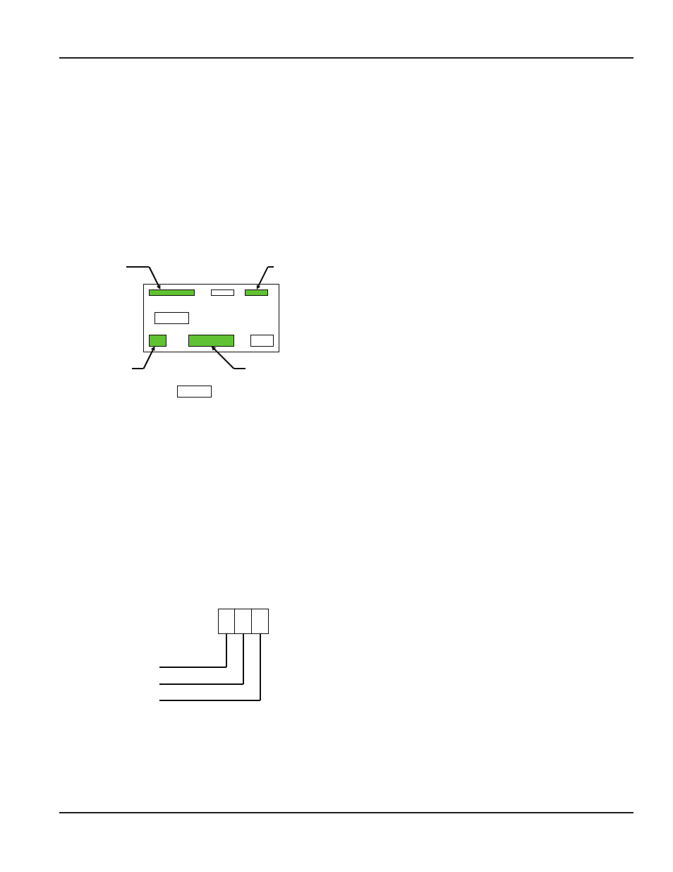
Terminal Block Layout
Control inputs
Transmitter input
AC power input
Relay output
Not used
The control input terminal block will require wiring only
if a remote Start or Stop input is used, if a lockout input is
needed, or if power up start must be enabled
The remote Start and Stop inputs duplicate the functions of
the front panel Start and Stop buttons as described above
However, there are some differences to be aware of The
front panel Start and Stop buttons require a second press of
the button within ten seconds of the first press to initiate a
start or stop The rear terminal Start and Stop inputs initiate
the function immediately The front panel Start and Stop
buttons act as momentary switches, which means that
the action occurs when the button is pressed, and is not
repeated until the button is released and then pressed again
The rear terminal inputs act as maintained inputs
If the Start terminal is switched to ground, the regeneration output will turn on and remain on as long as the input is
grounded A Stop input will always override a Start input, for as long as the Stop input is connected to ground
In the Auto mode, the output timer will not start timing until the Start input switch is opened Therefore, it is normally
recommended that remote Start and Stop input switches be momentary, rather than maintained
Lock inputs are treated as maintained inputs, and maintained switches should be used Lockout occurs immediately when the
lock input is active, and ends when the lock input goes inactive There are several variations of lock inputs They are discussed
in detail in the control input wiring section below Since the power up start function will normally always be used or not used,
use a jumper wire to enable power up start, or leave the terminal open to disable power up start
AC Power Input
L1 (hot)
L2 (neutral)
Ground
85-265 VAC
47-63 Hz
20 VA
12-24 AWG
User Manual
Page 7
April 2013