Repair parts lists – Badger Meter Registers User Manual
Page 3
3
4.
With long-nose pliers, disconnect wire lugs
from terminals on switch (Item 13).
5.
With small screwdriver, loosen screw hold-
ing ground wire (see Figure 2) and remove
screw and wire lug from bottom plate. Use
hold-down screwdriver to lift out screw.
6.
Loosen metal and nylon screws (Items 14 and
17) that anchor bottom plate to housing.
7.
The replacement gear train is a complete
assembly with mounting plate (Item 16).
Remove switch from existing plate (see instruc-
tion in Switch Replacement section below)
and mount on new assembly.
8.
Adjust switch as described in Switch
Replacement section.
9.
Install change gears in location as indicated
on nameplate.
10. Reassemble contactor assembly, reversing
the procedure outlined above. Make certain
nylon screw is in mounting hole under switch
lugs.
B.
SWITCH REPLACEMENT
1.
To replace switch, remove the entire gear
train assembly as explained in section "A".
2.
Remove two screws with hex nuts that hold
switch to bottom plate (Figure 3 on back
page). Install new switch.
3.
With both screws slightly loose, adjust
switch.
4.
Rotate cam (Figure 3) so rounded "corner" is
opposite switch.
5.
Now rotate switch into cam until normally-
open switch closes.
6.
Tighten the screw opposite pivot screw, then
the pivot screw itself.
7.
Reinstall gear train assembly in housing.
8.
Reconnect wires to switch. (See Figure 2 for
proper color coding.)
(Instructions continued on back page)
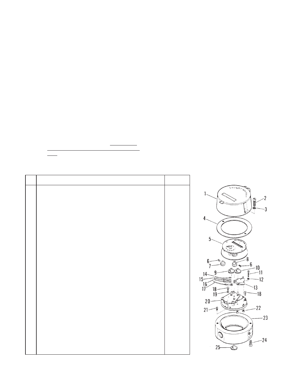
REPAIR PARTS LISTS
Item
No.
Name of Part
Part
Number
1
Hood Assembly, Register…………………………………………………
58234-002
2
Screw, Cover to Housing………………………………………………….
55048-251
3
Lock Washer………………………………………………………………..
55293-010
4
Gasket, Register Cover……………………………………………………
58404-001
5
Register Assembly (Specify meter size and registration required)…..
---------------
6
Setscrew, Change Gear…………………………………………………..
01065-000
7
Change Gear, Register (Specify number of teeth and diameter)……..
---------------
8
Change Gear, Electric Contactor (Specify number of teeth and
diameter)……………………………………………………………………
---------------
9
Change Gear, Driver (Specify number of teeth and diameter)…………
---------------
10
Change Gear, Driven (Specify number of teeth and diameter)………..
---------------
11
Screw, Pan Head, Switch…………………………………………………
55090-120
12
Lock Washer……………………………………………………………….
55291-005
13
Switch, Roller-Lever………………………………………………………..
24574-007
14
Wire Lead Assembly, Black (N.C.)………………………………………
23218-092
15
Wire Lead Assembly, Blue (N.O.)……………………………………….
23218-091
16
Wire Lead Assembly, Red (Common)…………………………………..
23218-090
17
Wire Lead Assembly, Green (Ground)…………………………………..
23218-093
18
Screw, Pan Head, Bottom Plate………………………………………….
55090-169
19
Lock Washer………………………………………………………………..
55281-007
20
Bottom Plate and Gear Train Assy. (1:1 Gear Ratio)………………….
58227-001
20
Bottom Plate and Gear Train Assy. (2:1 Gear Ratio)………………….
58227-004
20
Bottom Plate and Gear Train Assy. (9:1 Gear Ratio)………………….
58227-005
21
Screw, Nylon, Bottom Plate………………………………………………
32296-000
22
Nut, Hex., Bottom Plate…………………………………………………..
55002-032
23
Housing, Contactor…………………………………………………………
57724-002
24
Screw, Fill. Head (Register to housing)………………………………….
55048-276
25
Change Gear, Contactor to Meter (Specify number of teeth and
diameter)……………………………………………………………………
---------------