Operating instructions, General operating instructions, Shutdown instructions – Badger Meter Oscillating Piston Meter User Manual
Page 9: Operating instructions 9
OPERATING INSTRUCTIONS
General Operating Instructions
The instructions for operating an oscillating piston meter depend on the meter-accessory combination and the type of flow
control devices used in the facility piping In general, the operation is either manually controlled or accessory controlled
Manual operation applies to metering applications employing hand-operated valves or other manually-activated, flow-
regulating devices that are not functionally controlled by a meter-accessory device Accessory controlled operation is used in
metering applications involving meter-accessories that provide a signal output to activate and/or deactivate a valve or other
type of flow control device
REGARDLESS OF THE OPERATING PROCEDURE USED, THE VALVES OR DEVICES CONTROLLING THE FLUID FLOW
THROUGH THE METER MUST ALWAYS BE OPENED AND CLOSED SLOWLY TO PREVENT SHOCK LOADS THAT MAY
DAMAGE THE PISTON.
Manual Operation
Instructions are limited to the following start and stop procedures The procedures are intended for use in simple metering
applications where the flow of fluid through the meter is controlled by hand-operated valves located in the facility piping
upstream and downstream of the meter
1 Slowly open the upstream valve to apply fluid to the meter
2 Slowly open the downstream valve to initiate metering
3 Adjust the downstream valve so the flow rate does not exceed the flow rate specification of the meter
NOTE:
N
On meters equipped with an accessory device providing a totalizing indicator, the flow rate can be checked by timing
the number of gallons registered in one minute
4 To stop metering, slowly close the downstream valve; then close the upstream valve
Accessory Controlled Operation
The step-by-step operating procedures used in accessory controlled metering applications are dependent on the specific
function of the accessory employed and its electrical interconnection with a flow control device or devices See the
accessory's User Manual for specific operating instructions
Shutdown Instructions
If a meter is to be shut down for an extended period of time (particularly when the application involves the metering
of slurries or abrasive solutions), its measuring chamber should be thoroughly flushed out to prevent the settling
out of undissolved solids or the accumulation of corrosive deposits See
“Preventive Maintenance” on page 10
for
cleaning instructions
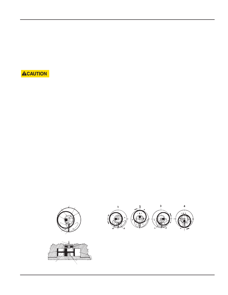
MEASURING CHAMBER
PISTON
CONTROL ROLLER
CYLINDRICAL
ABUTMENT
PISTON HUB
OUTLET PORT
PARTITION PLATE
INLET PORT
FOLLOWER MAGNET
MAGNET ASSEMBLY
HOUSING
MEASURING
CHAMBER
COVER
CONTROL ROLLER
CYLINDRICAL ABUTMENT
PISTON
Diagram 1
Spaces "a" and "c" are receiving liquid from the inlet port "1"
and spaces "b" and "d" are discharging liquid through the
outlet port "2".
Diagram 2
The piston has advanced and space "a" in connection with the
inlet port "1", has enlarged; and space "b" in connection with
the outlet port "2", has decreased. Spaces "c" and "d", which
have combined, are about to move into position to discharge
through the outlet port "2".
Diagram 3
Space "a" is still receiving liquid from the inlet port "1" and space
"c" is just opening again to the inlet port. Spaces "b" and "d" are
discharging through the outlet port "2".
Diagram 4
Liquid is being received by space "c" from the inlet port "1"
while liquid is being discharged from spaces "d" through the
outlet port "2". Spaces "a" and "b" have combined and are
about to discharge through the outlet port "2", as the piston
moves around to occupy the position as shown in Diagram 1
to begin the cycle again.
Figure 5: Shutdown Instructions
User Manual
Page 9
August 2013